KIA Niro: Relay Box (Passenger Compartment) Repair procedures
Fuse Inspection
- Check that the fuse holders are loosely held and that the fuses are securely fixed by the holders.
- Check that each fuse circuit has the exact fuse capacity.
- Check the fuses for any damage.
Warning
If a fuse is to be replaced, be sure to use a new fuse of the same capacity. Always identify the cause of the blown fuse and completely eliminate the problem before installing a new fuse.
Diagnosis with KDS
- In the body electrical system, failure can be quickly diagnosed by using
the vehicle diagnostic
system (KDS).
The diagnostic system (KDS) provides the following information.
(1) Self diagnosis : Checking failure and code number (DTC)
(2) Current data : Checking the system input/output data state
(3) Actuation test : Checking the system operation condition
(4) Additional function : Controlling other features including system option setting and zero point adjustment
- Select the 'Car model' and the 'Smart Junction Block (SJB)' to be checked in order to check the vehicle with the tester.
- Select the 'Current Data' menu to search the current state of the input/output data.
- To forcibly actuate the input value of the module to be checked, select option 'Actuation Test'
- If you want to change user option, select "user option".
Removal
Integrated Gateway & Power control Module (IGPM)
- Disconnect the negative (-) battery terminal.
- Remove the crash pad lower panel.
(Refer to Body - "Crash Pad Lower Panel")
- Remove the crash pad side switch (A) after loosening the mounting screw.
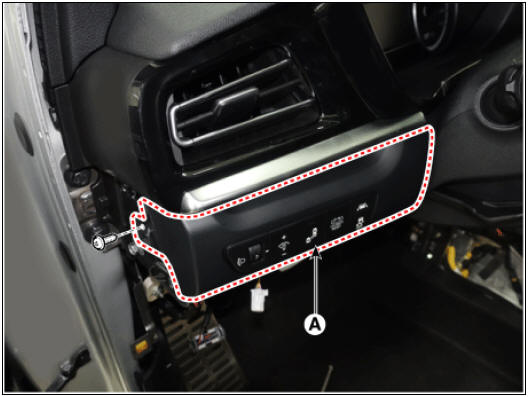
- Disconnect the crash pad side switch connector (A).
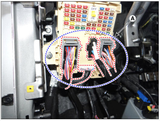
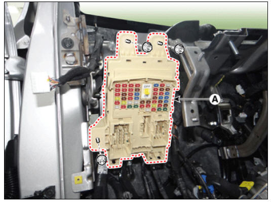
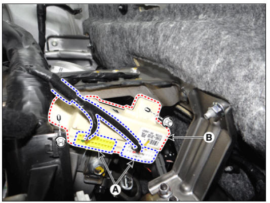
- Disconnect the connectors (A) from the fuse side of the IGPM.
- Remove the mounting clips (A).
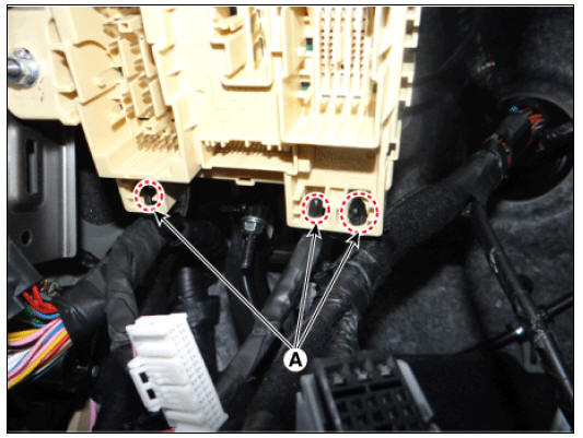
- Remove the IGPM (A) after loosening the mounting nuts.
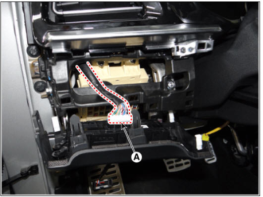
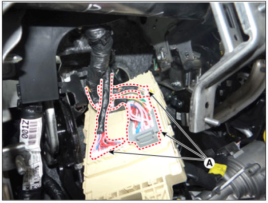
- Disconnect the connectors (A) from the back of the IGPM.
Installation
- Install in the reverse order of removal.
Circuit Diagram
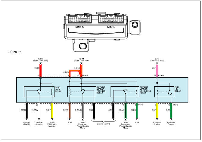
Description
The ICM relay is united with fuel filler door lock/unlock relay and outside mirror folding/unfolding relay which installed inside the crash pad.
Inspection
Outside Mirror Folding Relay
- After supplying power to between No. 8 and 17 ICM relay terminals, check that there is continuity between No. 16 and 19 terminals.
- After disconnecting power between No. 8 and 17 ICM relay terminals, check that there is no continuity between No. 16 and 19 terminals.
Outside Mirror Unfolding Relay
- After supplying power to between No. 8 and 17 ICM relay terminals, check that there is continuity between No. 15 and 18 terminals.
- After disconnecting power between No. 8 and 17 ICM relay terminals, check that there is no continuity between No. 15 and 18 terminals.
Removal
- Disconnect the negative (-) battery terminal.
- Remove the main crash pad assembly.
(Refer to Body - "Main Crash Pad Assembly")
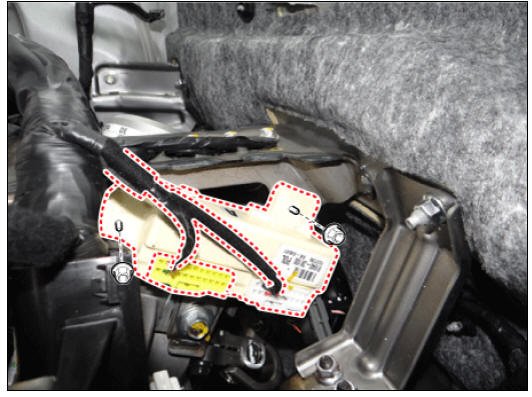
- Disconnect the connector (A) from the ICM relay.
- Remove the ICM realy (B) after loosening the mounting nuts.
Installation
- Install in the reverse order of removal.
READ NEXT:
 Headlamp Leveling System
Headlamp leveling actuator
Headlamp leveling switch
Connector and Terminal Function
Circuit Diagram
Headlamp Leveling Switch Repair procedures
Removal
Disconnect the negative (-) battery terminal.
Remove the crash pad low
Horn
Specifications
Horn switch
Horn relay (Built - in Metal Core Block PCB)
Horn (Low pitch)
Horn (High pitch)
Clock spring
Body Electrical System / Horn / Repair Procedures
Removal
Remove the front bumper cover.
(Refer to Bod
Ignition Switch
Ignition Switch / Repair Procedures
Inspection
Disconnect the key warning switch connector (A) and ignition switch
connector (B) from the steering column.
Check for continuity between the terminals.
If continuity is not specif
SEE MORE:
Limitations of Navigation-based Smart Cruise Control
Navigation-based Smart Cruise Control
may not operate properly under the following
circumstances:
The navigation is not working properly
Speed limit and road information in
the navigation is not updated
Map information is not transmitted
Crash Pad Main Lower Panel
Crash pad main lower panel
Replacement
Warning
Put on gloves to protect your hands.
Warning
Use a plastic panel removal tool to remove interior trim pieces
without marring the surface.
Be careful not to bend or scratch the trim
Categories
- Home
- KIA Niro EV, Hybrid - Second generation - (SG2) (2021-2024) - Owner's manual
- Kia Niro - First generation - (DE) (2017-2022) - Service and Repair Manual
- Contact Us