KIA Niro: Relay Box (Engine Compartment) Repair procedures
Kia Niro - First generation - (DE) (2017-2022) - Service and Repair Manual / Body Electrical System / Fuses And Relays / Relay Box (Engine Compartment) Repair procedures
Inspection
- Disconnect the negative (-) battery terminal.
- Pull out the relay from the engine compartment relay block.
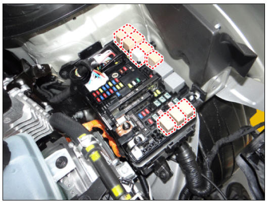
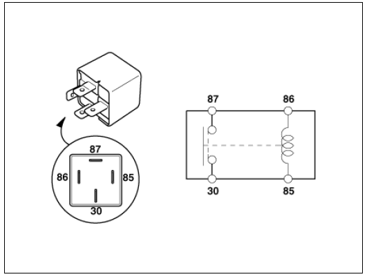
Power Relay (Type A)
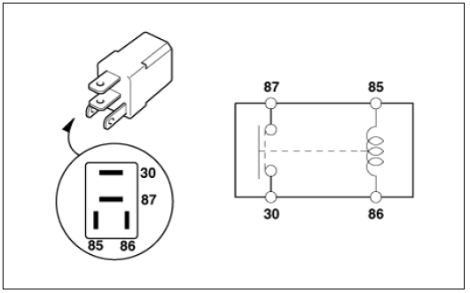
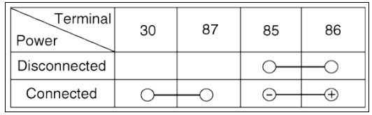
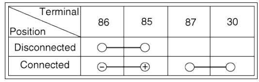
Check for continuity between the terminals.
- After supplying power to between No. 85 and 86 power relay terminals, check that there is continuity between No. 30 and 87 terminals.
- After disconnecting power between No. 85 and 86 power relay terminals, check that there is no continuity between No. 30 and 87 terminals.
Engine Room Relay Block
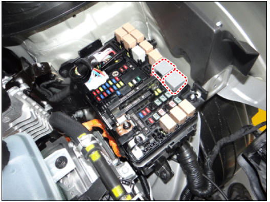
Power Relay (Type B)
Check for continuity between the terminals.
- After supplying power to between No. 85 and 86 power relay terminals, check that there is continuity between No. 30 and 87 terminals.
- After disconnecting power between No. 85 and 86 power relay terminals, check that there is no continuity between No. 30 and 87 terminals.
Metal Core PCB block
- Disconnect the negative (-) battery terminal.
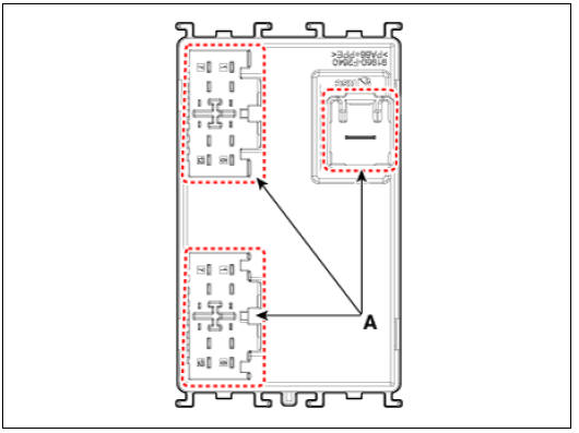
- Disconnect the PCB block connector (A).
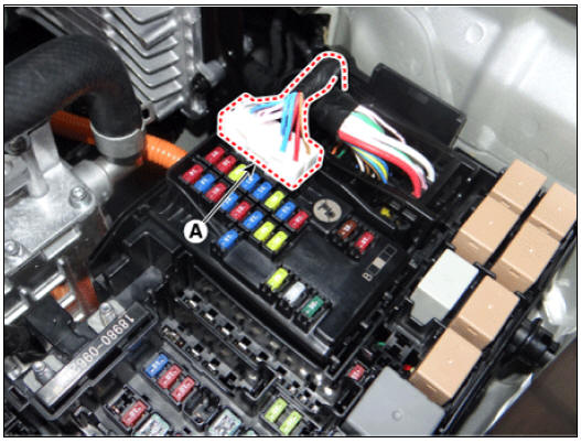
- Push the four hooks in the direction of the arrow and lift up the metal core PCB block (A).
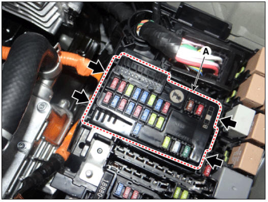
- Remove the metal core PCB block by disconnecting the connectors (A).
Fuse
- Check that the fuse holders are loosely held and that the fuses are securely fixed by the holders.
- Check that each fuse circuit has the exact fuse capacity.
- Check the fuses for any damage.
Warning
If a fuse is to be replaced, be sure to use a new fuse of the same capacity. Always identify the cause of the blown fuse and completely eliminate the problem before installing a new fuse.
READ NEXT:
 Multi Fuse
(Multi Fuse A, B)
Disconnect the negative (-) battery terminal.
Remove the power cable terminal (A) after loosening the nut from the
engine room fuse & relay
box.
Remove the multi fuse A (A) after pushing the hook.
Remo
Relay Box (Passenger Compartment)
IGPM
Description
Communication Network Diagram
Integrated Gateway & Power control Module (IGPM)
Integrated Gateway & Power control Module (IGPM) is a module that performs
the function of conventional Junction Block and
Relay Box (Passenger Compartment) Repair procedures
Fuse Inspection
Check that the fuse holders are loosely held and that the fuses are
securely fixed by the holders.
Check that each fuse circuit has the exact fuse capacity.
Check the fuses for any damage.
Warning
If a fuse is to be rep
SEE MORE:
Manual mode
Paddle shifter is used to shift without
taking your hands off the steering wheel.
Operation
Pull the right side (+) of the paddle
shifter once to shift up.
Pull the left side (-) of the paddle
shifter once to shift down.
Operating
Shift Lever | Shift Cable
Components
Shift lever knob & boots
Shift lever assembly
Shift cable assembly
Shift Lever Repair procedures
Removal
Shift the gear to "N".
Remove the knob (A) by pulling it in the direction of arrow af
Categories
- Home
- KIA Niro EV, Hybrid - Second generation - (SG2) (2021-2024) - Owner's manual
- Kia Niro - First generation - (DE) (2017-2022) - Service and Repair Manual
- Contact Us