KIA Niro: Rear Combination Lamp Repair procedures | Tail Lamp
Kia Niro - First generation - (DE) (2017-2022) - Service and Repair Manual / Body Electrical System / Lighting System / Rear Combination Lamp Repair procedures | Tail Lamp
Removal
Rear Combination Lamp (Outside)
- Disconnect the negative (-) battery terminal.
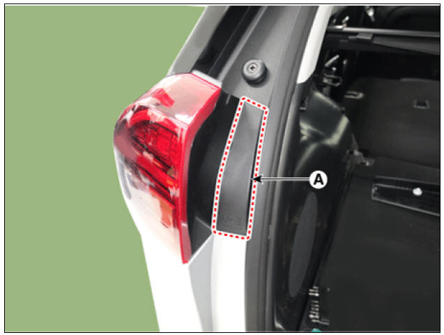
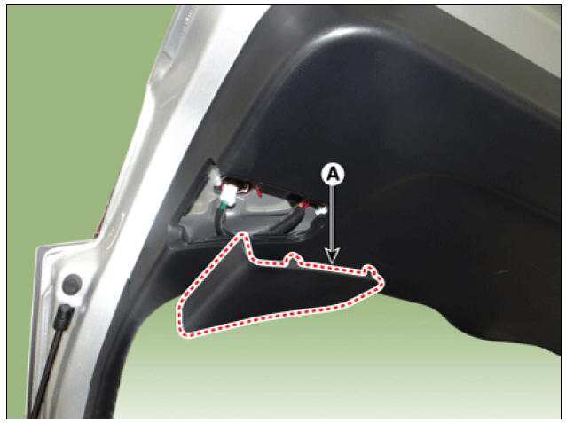
- Using a screwdriver or remover, remove the rear combination lamp cover (A).
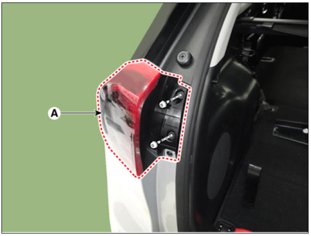
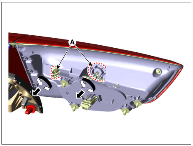
- Remove the rear combination lamp (A) after loosening the screws.
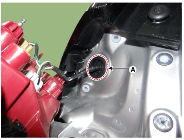
- Remove the rear combination lamp packing (A).
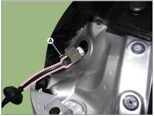
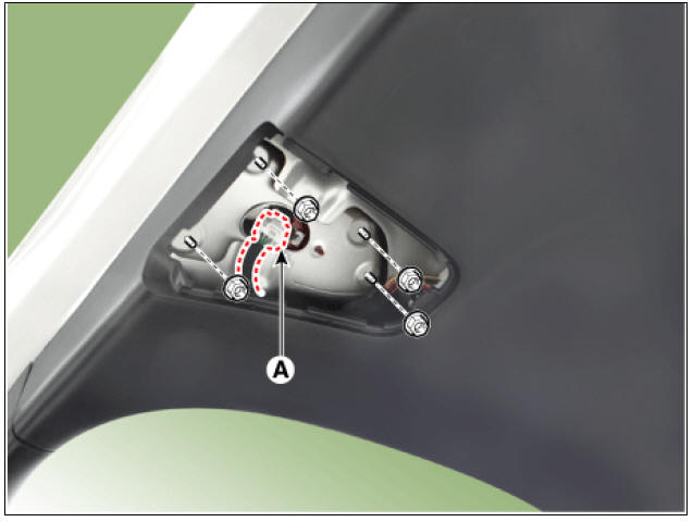
- Disconnect the rear combination lamp connector (A).
Rear Combination Lamp (Inside)
- Disconnect the negative (-) battery terminal.
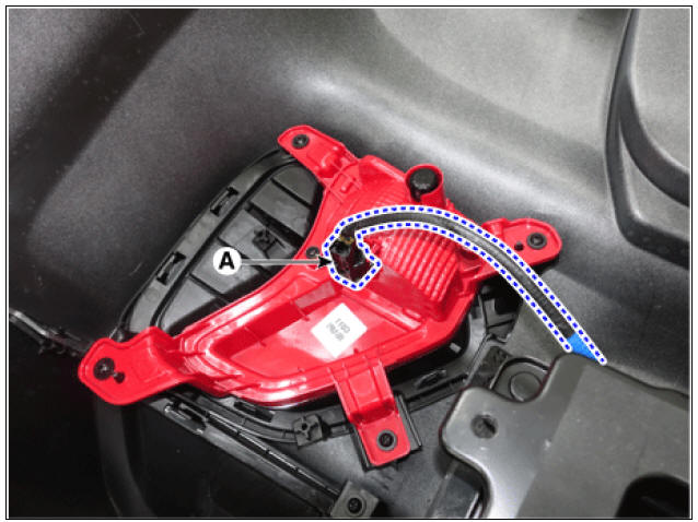
- Using a screwdriver or remover, remove the rear combination lamp cover (A).
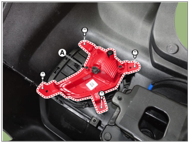
- Disconnect the connector (A) and then remove the rear combination lamp after loosening the nuts.
Back up lamp
- Disconnect the negative (-) battery terminal.
- Remove the rear bumper cover.
(Refer to Body - "Rear bumper Cover")
- Disconnect the back up lamp connector (A).
- Remove the back up lamp (A) after loosening the screws.
Installation
- Install in the reverse order of removal.
Tail Lamp
Replacement
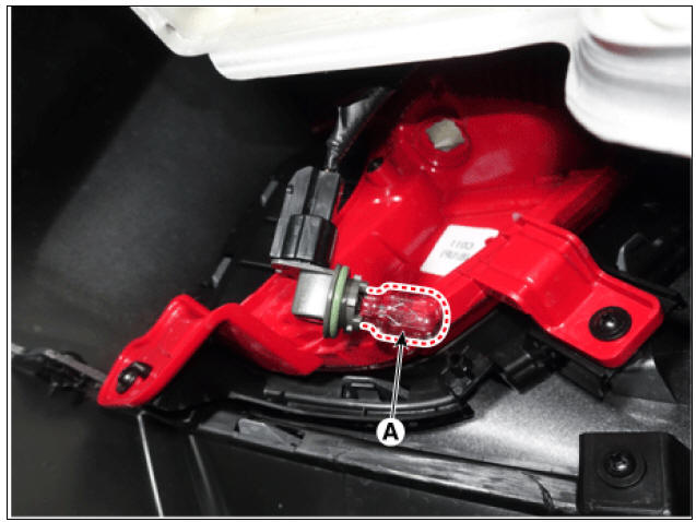
Tail Lamp
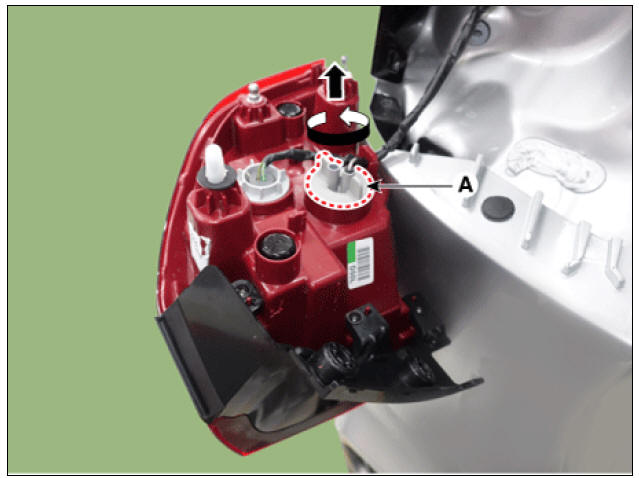
- Remove the inside rear combination lamp.
(Refer to Lighting System - "Rear Combination Lamp")
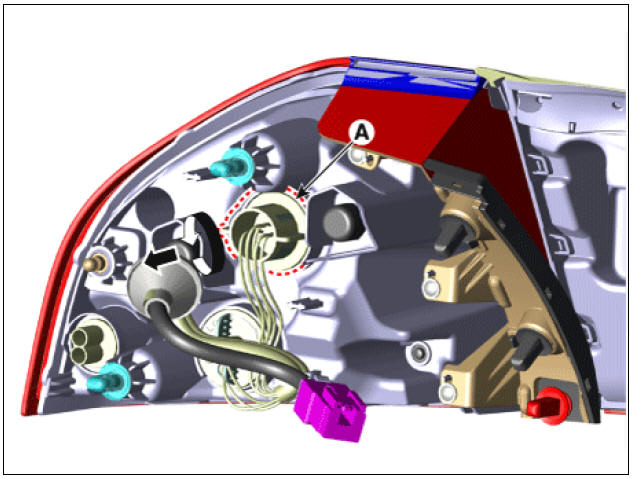
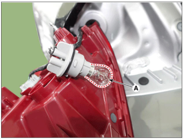
- Remove the tail lamp socket (A) by turning it in the counterclockwise direction.
- Replace the tail lamp bulb (A).
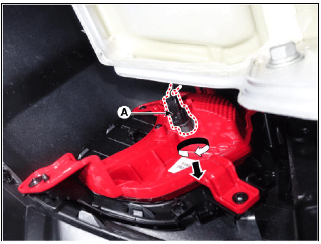
Tail Lamp & Stop Lamp
- Remove the outside rear combination lamp.
(Refer to Lighting System - "Rear Combination Lamp")
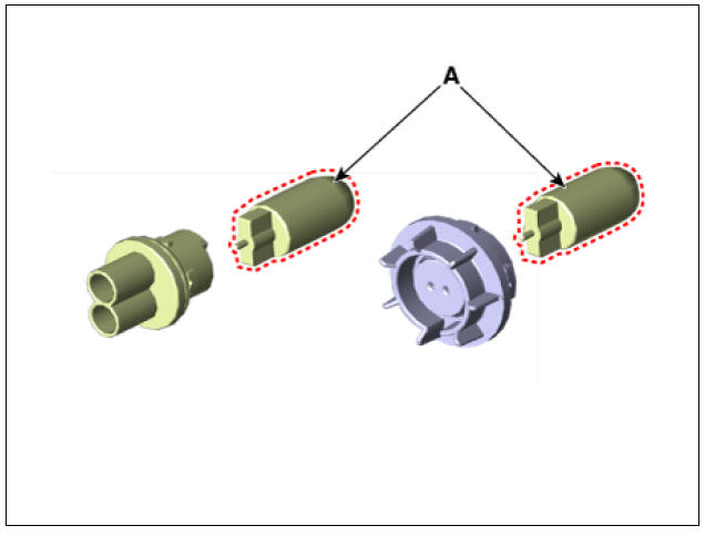
- Remove the tail lamp & stop lamp socket (A) by turning it in the counter clockwise direction.
- Replace the tail lamp & stop lamp bulb (A).
Turn Signal Lamp
- Remove the outside rear combination lamp.
(Refer to Lighting System - "Rear Combination Lamp")
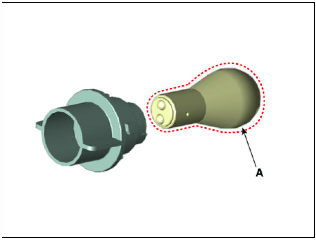
- Remove the turn signal lamp socket (A) by turning it in the counter clockwise direction.
- Replace the turn signal lamp bulb (A).
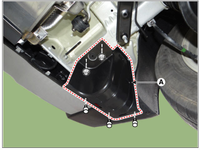
Back-up Lamp
- Remove the rear bumper under cover (A).
LH
RH
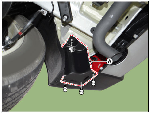
- Remove the back-up lamp socket (A) by turning it in the counterclockwise direction.
- Replace the back-up lamp bulb (A).
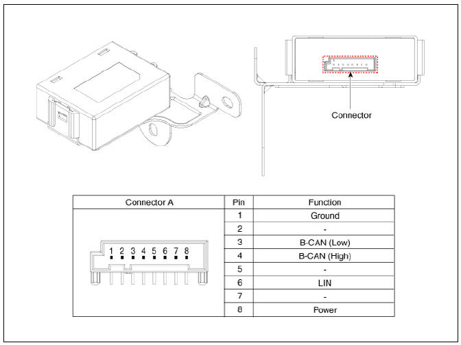
Connector and Terminal Function
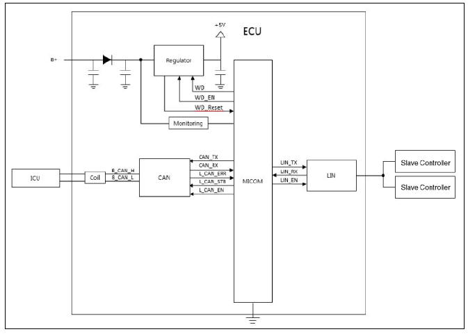
Circuit Diagram
Removal
- Remove the glove box housing.
(Refer to Body - "Glove box housing")
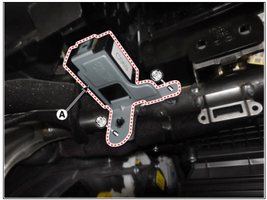
- Remove the mood lamp unit (A) after loosening the mounting nuts.
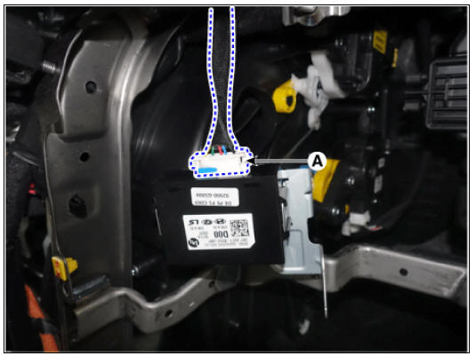
- Disconnect the connector (A) from the mood lamp unit.
Installation
- Install in the reverse order of removal.
Circuit Diagram
READ NEXT:
 Multifunction Switch
Specifications
Multifunction Switch / Components And Components Location
Steering column shaft
Lighting switch
Wiper/Washer switch
Screws
Clock spring
LHD
RHD
Multifunction Switch / Repair Procedures
Removal
Disconn
Power Door Locks
Power Door Locks / Components And Components Location
Driver power window switch
Assist power window switch
Integrated Gateway & Power control Module (IGPM)
Door lock knob
Tailgate latch assembly
Door latch assembly
Door lock/
SEE MORE:
Highway Driving Assist settings
Highway Driving Assist is designed to
help detect vehicles and lanes ahead,
and help maintain distance from the
vehicle ahead, maintain the set speed,
help center the vehicle in the lane while
driving on the highway (or motorway).
NOTICE- (
Crankshaft
Check the crankshaft bearing oil clearance.
(1) To check main bearing-to-journal oil clearance, remove the lower
crankcase and lower bearings.
(2) Clean each main journal and bearing with a clean shop towel.
(3) Place one strip of plastigag
Categories
- Home
- KIA Niro EV, Hybrid - Second generation - (SG2) (2021-2024) - Owner's manual
- Kia Niro - First generation - (DE) (2017-2022) - Service and Repair Manual
- Contact Us