KIA Niro: Multimedia Jack
Circuit Diagram

Description
The multimedia jack on the console upper cover is for customers who like to listen to external portable music players like the MP3 etc., through the vehicle's sound system when it is linked to this jack. The customer has this added option.
In case of distorted sound coming from the AUX-linked external music players, the audio unit may not be defective but the output level of the player does not match the specification of the AUX.

Multimedia Jack Repair procedures
Removal
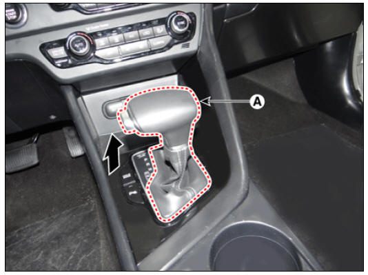
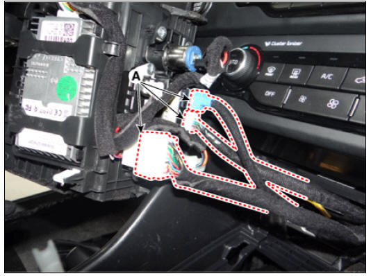
- Remove the gear knob (A) by pull both of it up after removing the boots from the console upper cover.
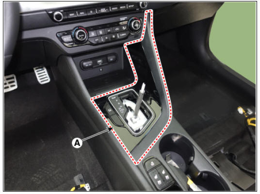
- Remove the console upper cover (A).
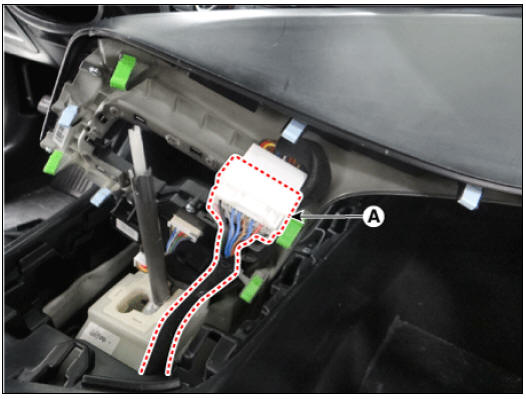
- Disconnect the connector (A) from the console upper cover.
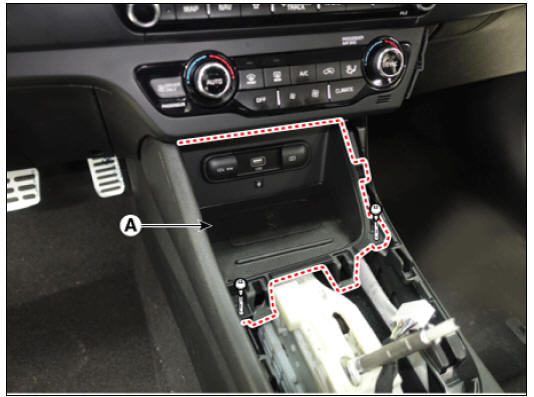
- Remove the console tray (A) after loosening the mounting screws.
- Disconnect the connectors (A) from the console tray.
- Remove the multimedia jack (A) after releasing the fixed hooks.

Installation
- Install in the reverse order of removal.
Mic Repair procedures
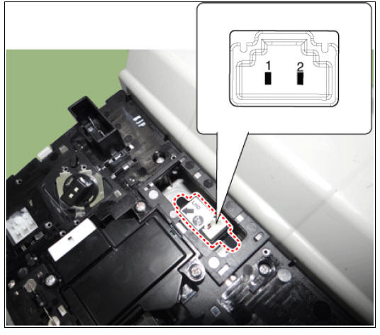
Inspection
- Remove the overhead console lamp.
(Refer to Lighting System - "Overhead Console Lamp")
- Check the continuity of between terminals.

Removal
- Remove the overhead console lamp.
(Refer to Lighting System - "Overhead Console Lamp")
- Remove the hands-free mic (A) after loosening the mounting screws.

Installation
- Install in the reverse order of removal.
READ NEXT:
 Body Control Module (BCM) / Description And Operation
Specifications
Schematic Diagrams
Connector Pin Information
Description
Body Control Module (BCM) function
Washer Linked Wiper
If the washer switch is pressed ON for 0.06-0.2 second with the
Body Control Module (BCM) / Repair Procedures
Removal
Disconnect the negative (-) battery terminal.
Remove the glove box housing.
(Refer to Body - "Glove Box Housing")
Disconnect the blower motor connector (A).
Disconnect the body control module connectors (A).
SEE MORE:
Forward Collision-Avoidance Assist malfunction and limitations
(Kia Niro Hybrid only)
A: Check forward safety systems
When Forward Collision-Avoidance
Assist is not working properly, the warning
message will appear, and the ( )
and ( ) warning lights will appear
on
the cluster. Kia recommends visitin
Cylinder Head
Inspect for flatness.
Using a precision straight edge and feeler gauge, measure the contacting
surface of the cylinder block and check
the manifolds for warpage.
If the flatness is greater than maximum, replace the cylinder head.
Fla
Categories
- Home
- KIA Niro EV, Hybrid - Second generation - (SG2) (2021-2024) - Owner's manual
- Kia Niro - First generation - (DE) (2017-2022) - Service and Repair Manual
- Contact Us