KIA Niro: Body Control Module (BCM) / Repair Procedures
Kia Niro - First generation - (DE) (2017-2022) - Service and Repair Manual / Body Electrical System / Body Control Module (BCM) / Body Control Module (BCM) / Repair Procedures
Removal
- Disconnect the negative (-) battery terminal.
- Remove the glove box housing. (Refer to Body - "Glove Box Housing")
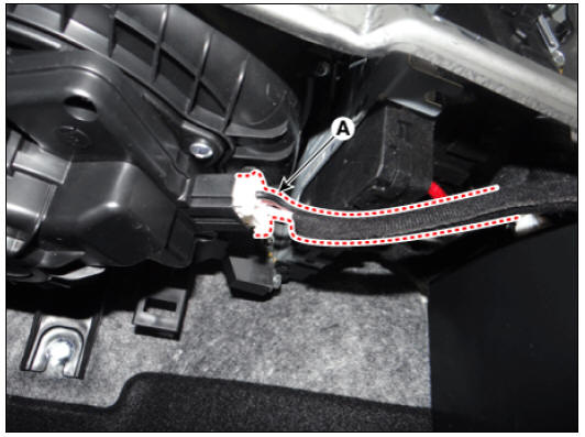
- Disconnect the blower motor connector (A).
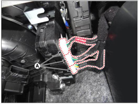
- Disconnect the body control module connectors (A).
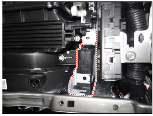
- Remove the body control module (A) after loosening the mounting bolts and nuts.
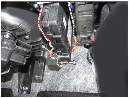
- Remove the body control module (B) after disconnecting the connector (A).

Installation
- Install in the reverse order of removal.
BCM Diagnosis With KDS
- In the body electrical system, failure can be quickly diagnosed by using the vehicle diagnostic system (KDS).
The diagnostic system (KDS) provides the following information.
(1) Self diagnosis : Checking failure and code number (DTC)
(2) Current data : Checking the system input/output data state
(3) Actuation test : Checking the system operation condition
(4) Additional function : Controlling other features including system option setting and zero point adjustment
- Select the "Car model" and the 'Body Control Module (BCM)' to be checked in order to check the vehicle with the tester.
- Select the 'Current Data' menu to search the current state of the input/output data.
- If you want to change user option, select "user option".
READ NEXT:
 Button Engine Start System / Description And Operation
Button Engine Start System / Components And Components Location
Body control module (BCM)
Smart key unit (SMK)
Interior antenna 1
Interior antenna 2
FOB key
Start Stop Button (SSB)
Door handle & door antenna
Bumper ant
Start/Stop Button | ESCL (Electronic Steering Column Lock)
Start/Stop Button Repair procedures
Removal
Disconnect the negative (-) battery terminal.
Remove the crash pad garnish assembly (RH). (Refer to Body - "Crash Pad Garnish (RH)")
Remove the start/stop button.
(1) Push
SEE MORE:
Gear Actuator Assembly, Repair procedures
Component Location
Gear actuator assembly
Shift motor 2 (Even)
Shift motor 1 (Odd)
Select solenoid 2 (Even)
Select solenoid 1 (Odd)
Specification
Gear Actuator Assembly Description and operation
Description
Power/Charge
gauge
The Power/Charge Gauge shows the
energy consumption rate of the vehicle
and the charge/discharge status of the
regenerative brakes.
Power: It shows the energy consumption
rate of the vehicle when driving
uphill or accelerating. The mor
Categories
- Home
- KIA Niro EV, Hybrid - Second generation - (SG2) (2021-2024) - Owner's manual
- Kia Niro - First generation - (DE) (2017-2022) - Service and Repair Manual
- Contact Us