KIA Niro: Instrument Cluster Description and operation
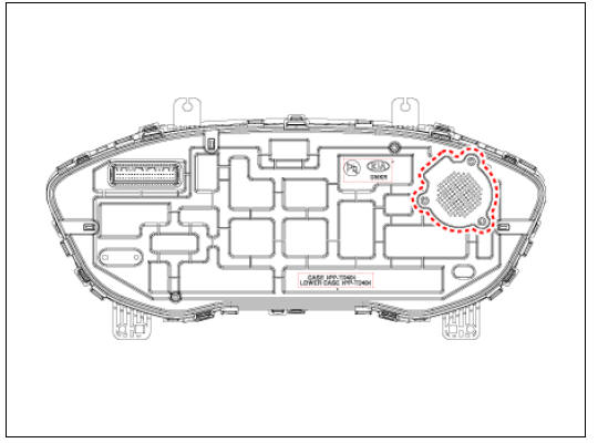
Instrument Cluster Components and components location
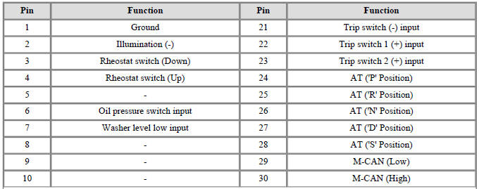
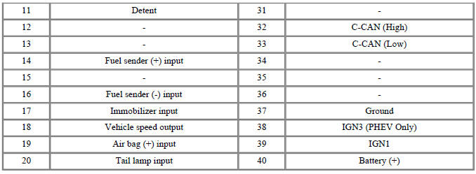
Connector and Terminal Function
Instrument Cluster Description and operation
Description
Main Function
- High speed CAN communication (C-CAN)
(1) Custom Function : car seats linked to getting on/off motion, Welcome Light etc.
(2) LKA: Lane Keeping Assist
(3) PDW: Parking Distance Warning
- Low speed CAN communication (M-CAN)
(1) AV : Audio / Video Multimedia information Display
(2) TBT : Turn By Turn Navigation Information Display
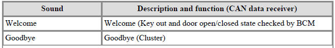
- Sound output
Various alarms and sound effects are issued through the cluster speaker.
- User Setting Mode (USM)
Setting can be changed by using switchs (Menu, UP, Down and OK button). There are many items (for example, In/Out Seat Synchronization, In/Out Steering Wheel Synchronization, Auto Door Lock, Auto Door Lock Deactivate, Head Lamp Escort, Welcome Light, Welcome Sound, One Touch Turn Signal, Average Fuel Consumption Auto Reset, Brightness, and Content Setup) that can be set and customized. The signal flow during setting is as follows.
(1) UMS settings are set, they are transmitted to BCM.
(2) BCM transmits the settings via B-CAN to the relevant modules.
(3) The module completes setting and transmits the modified setting to BCM.
(4) BCM transmits the final settings via C-CAN to the cluster.
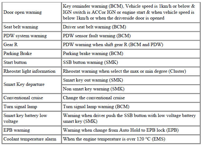
Warning
The cluster communicates directly with C-CAN units.
Hybrid Mian Features
- ECO and power guage
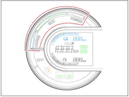
(1) It displays the degree of economic driving by identifying the status of a driver's operation, depending on a vehicle's driving conditions (e.g., required power, system efficiency and charging).
(2) It leads to economic driving by informing the driver of the optimal driving conditions depending on the vehicle's conditions.
(3) It displays that ECO guide and power segment will operate during driving, and also indicates the state of regenerative braking when a charge zone is instructed while driving.
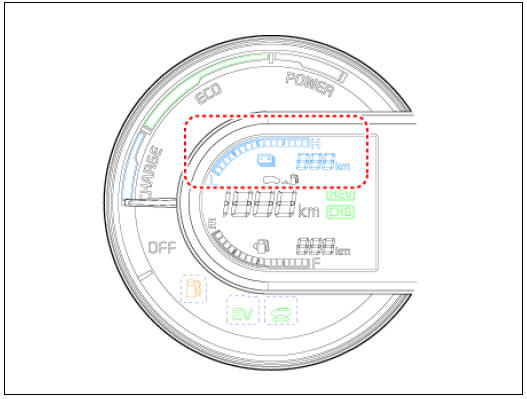
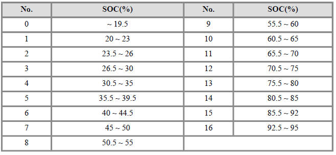
- SOC(State of Charge) guage
(1) It displays the amount of charge of high-voltage battery.
(2) It displays the charged amount of SOC received from BMS module on the digital gauge in the instrument cluster (as follows).
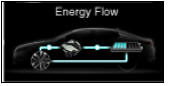
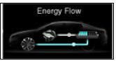
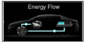
- Energy Flow
(1) It displays graphical energy flow of an HEV vehicle to inform the driver of the vehicle information.
(2) It leads to economic driving by showing the energy flow diagram by means of intuitive images.
(3) HCU module receives operation mode CAN signals to implement any relevant animation.
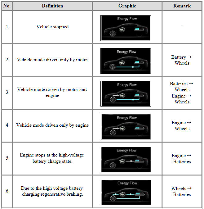
- Vehicle stopped
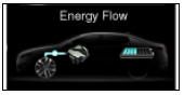
- Vehicle mode driven only by motor
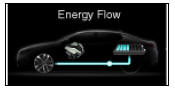 Battery →
Wheels
Battery →
Wheels - Vehicle mode driven by motor and
engine
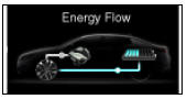 Batteries →
Wheels
Engine →
Wheels
Batteries →
Wheels
Engine →
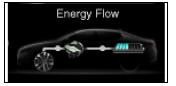
Wheels - Vehicle mode driven only by engine
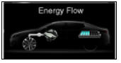 Engine →
Wheels
Engine →
Wheels - Engine stops at the high-voltage
battery charge state.
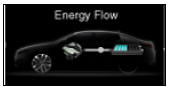 Engine →
Batteries
Engine →
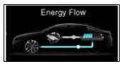
Batteries - Due to the high voltage battery
charging regenerative braking
 Wheels
→
Batteries
Wheels
→
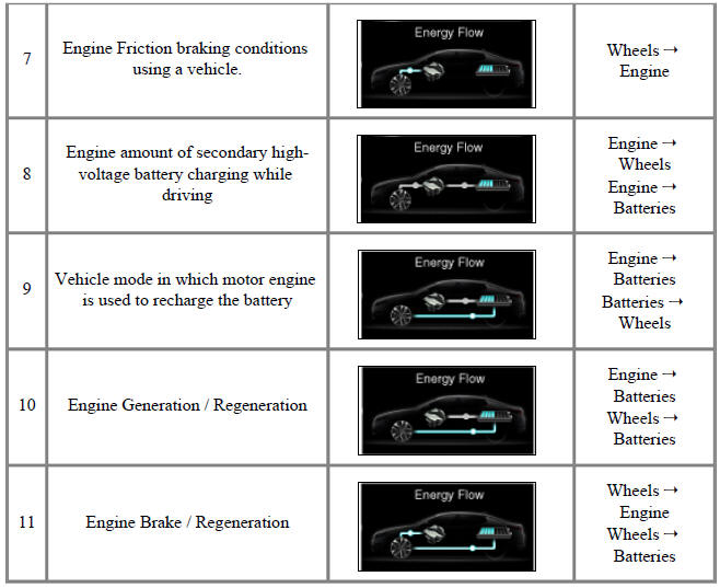
Batteries - Engine Friction braking conditions
using a vehicle.
 Wheels →
Engine
Wheels →
Engine - Engine amount of secondary highvoltage
battery charging while
driving
 Engine →
Wheels
Engine →
Batteries
Engine →
Wheels
Engine →
Batteries - Vehicle mode in which motor engine
is used to recharge the battery
 Engine
→
Batteries
Batteries →
Wheels
Engine
→
Batteries
Batteries →
Wheels - Engine Generation / Regeneration
 Engine →
Batteries
Wheels →
Batteries
Engine →
Batteries
Wheels →
Batteries - Engine Brake / Regeneration
 Wheels
→
Engine
Wheels →
Batteries
Wheels
→
Engine
Wheels →
Batteries
READ NEXT:
 Instrument Cluster Repair procedures
Removal
Warning
Put on gloves to protect your hands.
When removing with a flat-tip screwdriver or remover, wrap
protective tape around the tools to prevent damage to
components.
Instrument Cluster
Disconnect the negative (-) batter
Indicators And Gauges - Troubleshooting
Troubleshooting
Error Item:
Screen display
Failure
symptom:
LCD screen
does not turn
on
Inspection items:
Connector
attachments
Components
Detailed inspections:
Check the
connector
attachments
Check B+, IGN and
SEE MORE:
Rear Shock Absorber Repair procedures
Rear Suspension System / Components And Components Location
Stabilizer bar
Rear sub frame
Rear upper arm
Rear shock absorber
Rear axle
Assist arm
Trailing arm
Coil spring
Rear Shock Absorber Repair procedures
Removal
Dis
Opening the hood
(Kia Niro Hybrid only)
Hood release lever
Hood secondary latch
Hood
Operation
Pull the hood release lever (1).
Push the secondary latch (2) to the
left.
Lift the hood (3) upwards.
Go to the front of the vehicle, raise
Categories
- Home
- KIA Niro EV, Hybrid - Second generation - (SG2) (2021-2024) - Owner's manual
- Kia Niro - First generation - (DE) (2017-2022) - Service and Repair Manual
- Contact Us