KIA Niro: High Voltage Battery Module Balancing & Voltage Measurement
- After removing the defective module from the HV battery pack make carefully a visual check and then put back it into the safety disposal box.

Warning
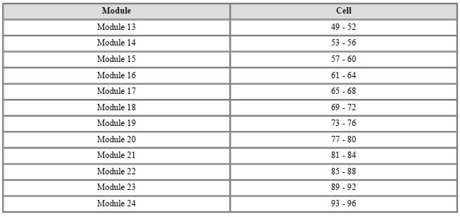
- The cell quantity varies per module number. Check before conducting procedure.
- Handle the module with care.
- Using a multimeter, measure the voltage of the remaining good battery modules with the same quantity of cells inside
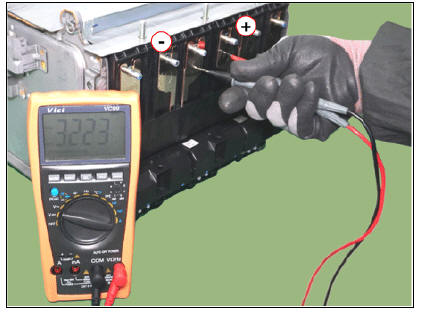
- After measuring the voltage levels of the remaining good battery modules, calculate the target voltage level by using the averaging formula as below shown:
Formula to be used for calculation: Target Voltage = (Voltage of remaining good module 1 + Voltage of remaining good module 2) / 2
Sub High Voltage Battery Pack Assembly

Main High Voltage Battery Pack Assembly

Warning
Not required to measure the Max and Min voltage level by GDS/KDS, as the target voltage level will be calculated after measuring and averaging the voltage level of the other remaining good modules and.
- After the target voltage is calculated, it can be then input to the charger / discharger. Please refer level and correctly connect the new module to the charging / discharging device.
- After the charging or discharging of the new module is finished, check again with a multimeter the voltage level of. If it is like calculated average, then it can be re-assembled into the HV battery pack.
Reassembly
Warning
- Be sure to read and follow the "General Safety Information and Caution" before doing any work related with the high voltage system. Failure to follow the safety instructions may result in serious electrical injuries.
- Be sure to shut off the high voltage before doing any work related with the high voltage system(Refer to "High Voltage Shut-off Procedure"). Failure to follow the safety instructions may result in serious electrical injuries.
- Install the battery pack assembly in the reverse order of removal.
Inspection
Battery Pack Assembly Troubleshooting Chart

Warning
- For SOC check, refer to "SOC Inspection"
- For voltage check, refer to "Battery Voltage Inspection"
- For battery voltage sensing circuit, refer to "Voltage Sensing Circuit Inspection"
- For isolation resistance check, refer to "Isolation Resistance Inspection"
SOC Level and Follow-up

SOC Inspection
- Connect the KDS to the Data Link Connector (DLC).
- Turn the ignition switch ON.
- Check the SOC in KDS service data.
SOC : Above 5%

Battery Voltage Inspection
- Connect the KDS to the Data Link Connector (DLC).
- Turn the ignition switch ON.
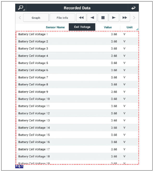
- Check the cell and pack voltage in KDS service data.
Cell Voltage : 2.5 - 4.2V
Pack Voltage : Above 360V
Cell volage deviation : 40 mV or less

Voltage Sensing Circuit Inspection
- Shut off the high voltage circuit.
(Refer to "High Voltage Shutoff Precedure")
- Remove the battery temperature sensor.
(Refer to "Battery Temperature Sensor")
- Check the continuity of the wiring between the harness connectors of the module and BMS ECU.
Specification : below 1Ω
- Connect the harness connectors to the BMS ECU.
- For checking the short circuit to ground, measure resistance between the module harness connectors and chassis ground.
Specification : 1MΩ or higher

Isolation Resistance Inspection
- Connect the KDS to the Data Link Connector (DLC).
- Turn the ignition switch ON.
- Check the isolation resistance in KDS service data.
Isolation Resistance : Around 1.0 MΩ

READ NEXT:
 Power Relay Assembly (PRA)
Description
The Power Relay Assembly (PRA) consists of the positive and negative main
relays, pre-charge relay, pre-charge resistor and
battery current sensor. It is located inside the battery pack assembly and
controls the high voltage power c
Main High Voltage Battery Front Cover | Sub High Voltage Battery upper Cover
Removal
Warning
Be sure to read and follow the "General Safety Information and Caution" before doing any work related with the high voltage system. Failure to follow the safety instructions may result in serious electrical inj
SEE MORE:
General safety information and caution
Precautions
General Precautions
Please read the following precautions carefully before performing the airbag
system service.
Observe the instructions described in this manual, or the airbags could
accidentally deploy and cause damage or injur
Warning and indicator lights (Kia Niro EV)
Once you set the vehicle to the ON position, the symbols shown below will
light up. If these symbols remain on or malfunction, we
recommend having the vehicle inspected by an authorized Kia dealer/service
partner.
The information provided may
Categories
- Home
- KIA Niro EV, Hybrid - Second generation - (SG2) (2021-2024) - Owner's manual
- Kia Niro - First generation - (DE) (2017-2022) - Service and Repair Manual
- Contact Us