KIA Niro: Heater Pipe | Active Air Flap (AAF) Repair procedure
- Disconnect the battery negative terminal.
- Loosen the drain plug, and drain the engine coolant. Remove the reservoir cap to help drain the coolant faster.
(Refer to Cooling System - "Coolant")
- Remove the air cleaner assembly.
(Refer to Intake and Exhaust System - "Air Cleaner")
- Remove the water temperature control assembly.
(Refer to Cooling System - "Water Temperature Control Assembly")
- Remove the intake manifold.
(Refer to Intake and Exhaust System - "Intake Manifold")
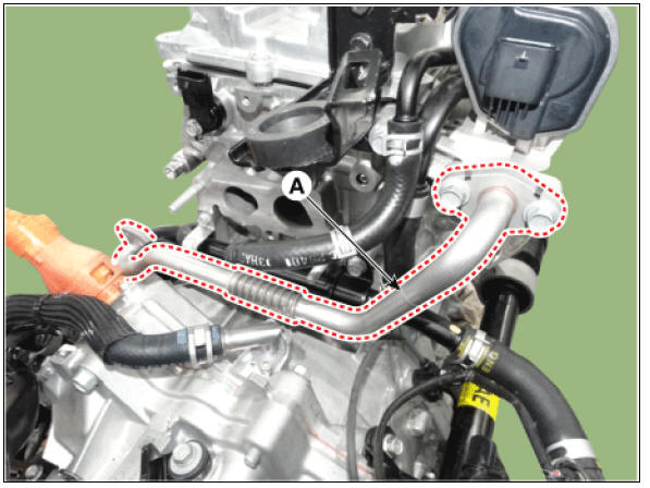
- Remove the electric EGR control valve cooler pipe (A).
Tightening torque : 18.6 - 23.5 N.m (1.9 - 2.4 kgf.m, 13.7 - 17.4 lb-ft)
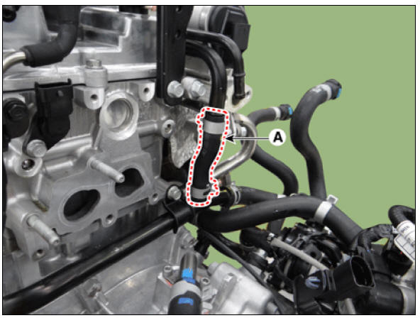
- Disconnect the coolant hose (A).
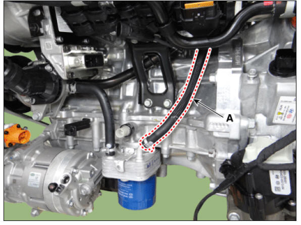
- Disconnect the oil cooler hose (A).
- Remove the heater pipe (A).
Tightening torque : 18.6 - 23.5 N.m (1.9 - 2.4 kgf.m, 13.7 - 17.4 lb-ft)

Warning
- When assembling the heater pipe, make sure that there is no foreign substance in the O-ring gasket.
- Be sure to apply antifreeze on the O-ring gasket before inserting the heater pipe to the water pump housing.
- Install in the reverse order of removal.
- Fill the radiator with coolant and check for leaks.
(Refer to Cooling System - "Coolant")
- Start engine and check for leaks.
- Recheck the coolant level.
Active Air Flap (AAF) Repair procedures
Active Air Flap (AAF) Description and operation
Description
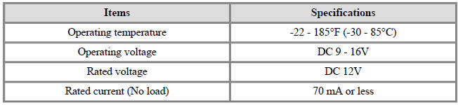
The system receives information from ECU, FATC, TCU, MCU and LDC via CAN communication .
With this information, the active air flap (AAF) controls the motor properly then the air flaps adjust air flow from radiator grille.
During high speed driving, it will reduce the air resistance by closing the air flaps. This improves the fuel efficiency and enhance the driving stability. If overheat occurs, the system will open the air flaps to drop the temperature.
During the A/C operation, the system will open the air flaps to maintain the refrigerant pressure. The system will close the air flaps to warm up the engine rapidly during cold start.
Specifications

Schematic Diagram
Active Air Flap (AAF) Repair procedures
Removal and Installation
- Remove the air duct.
(Refer to Intake and Exhaust System - "Air Cleaner")
- Remove the front bumper cover.
(Refer to Body (Interior and Exterior) - "Front Bumper Cover")
- Disconnect the high pitch horn connector (A).
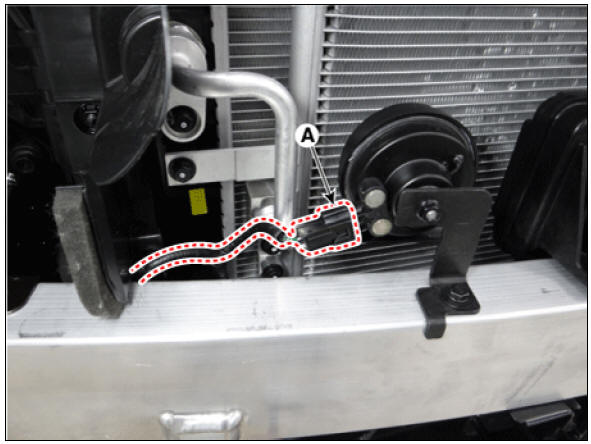
- Disconnect the low pitch horn connector (A).
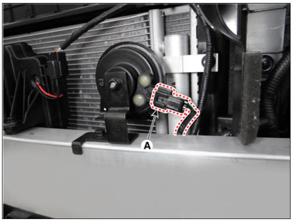
- Disconnect the virtual engine sound speaker (VESS) speaker connector (A).
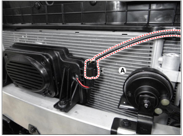
- Disconnect the advents smart cruise control (ASCC) connector (A)
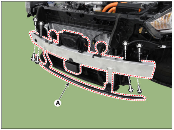
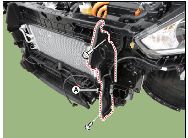
- Remove the front bumper beam (A).
Tightening torque : 7.8 - 9.8 N*m (0.8 - 1.0 kgf*m, 5.8 - 7.2 lb*ft)
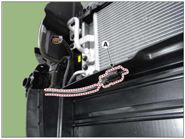
- Remove the ambient temperature sensor (A)
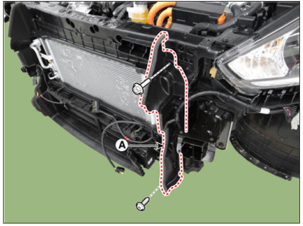
- Remove the air guard (A).
Tightening torque : 3.9 - 5.9 N*m (0.4 - 0.6 kgf*m, 2.9 - 4.3 lb*ft)
RH

LH
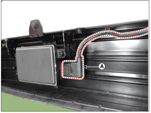
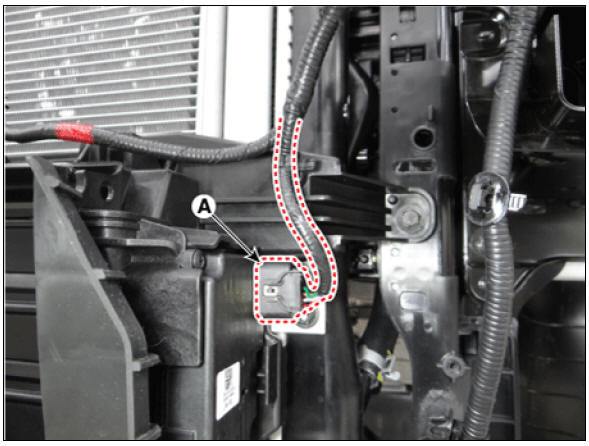
- Disconnect the active air flap (AAF) connector (A).
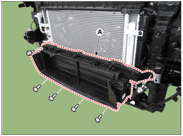
- Remove the active air flap (AAF) (A).
Tightening torque : 7.8 - 9.8 N*m (0.8 - 1.0 kgf*m, 5.8 - 7.2 lb*ft)
- Install in the reverse order of removal.
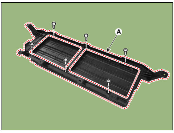
Disassembly
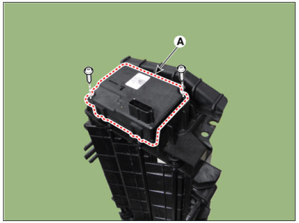
- Remove the active air flap (AAF) actuator (A).
Tightening torque : 1.5 - 2.5 N*m (0.15 - 0.25 kgf*m, 1.1 - 1.8 lb*ft)
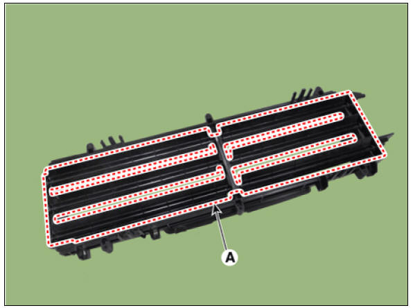
- Remove the active air flap (AAF) duct (A).
Tightening torque : 2.0 - 3.9 N*m (0.2 - 0.4 kgf*m, 1.4 - 2.9 lb*ft)
- Remove the air flap (A).
- Assemble in the reverse order of disassembly.
Active Air Flap (AAF) - Troubleshooting
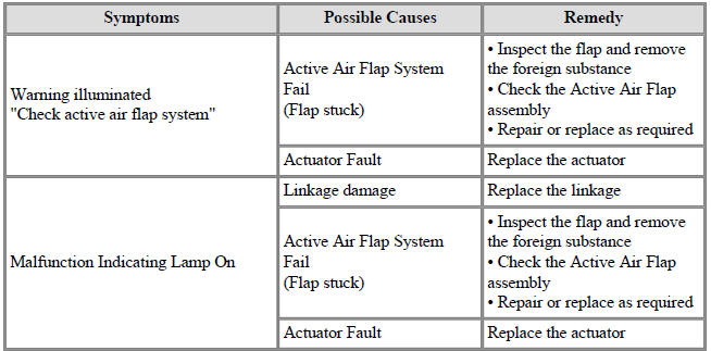
Symptoms:
Warning illuminated "Check active air flap system"
Possible Causes :
Active Air Flap System Fail (Flap stuck)
Remedy :
-
Inspect the flap and remove the foreign substance
-
Check the Active Air Flap assembly
-
Repair or replace as required
Possible Causes :
Actuator Fault
Remedy :
Replace the actuator
Symptoms:
Malfunction Indicating Lamp On
Possible Causes :
Linkage damage
Remedy :
Replace the linkage
Possible Causes :
Active Air Flap System Fail (Flap stuck)
Remedy :
-
Inspect the flap and remove the foreign substance
-
Check the Active Air Flap assembly
-
Repair or replace as required
Possible Causes :
Actuator Fault
Remedy :
Replace the actuator
After performing repairs, clear Diagnostic Trouble Codes (DTC) and check the warning and
Malfunction Indicating Lamp.
READ NEXT:
 Fly Wheel Repair procedures
Components
Water jacket insert
Cylinder block
Oil ring
Rear oil seal
Crankshaft upper bearing
Thrust bearing
Crankshaft
Pilot bearing
Crankshaft lower bearing
Crankshaft lower bearing cap
Ladder frame
Piston ring
Pisto
SEE MORE:
Vehicle safety system
Anti-lock Brake System (ABS)
The Anti-lock Brake System (ABS) prevents
the wheels from locking to steer
and stabilize the vehicle.
If the ABS warning light ( ) stays
on,
contact a professional workshop as soon
as possible. Kia recommends to
Smart Cruise Control malfunction
A: Check Smart Cruise Control System
When Smart Cruise Control is not working
properly, the warning message will
appear, and the ( ) warning light
will
appear on the cluster. Have Smart
Cruise Control be inspected by a professional
worksh
Categories
- Home
- KIA Niro EV, Hybrid - Second generation - (SG2) (2021-2024) - Owner's manual
- Kia Niro - First generation - (DE) (2017-2022) - Service and Repair Manual
- Contact Us