KIA Niro: Front Wheel Speed Sensor
Kia Niro - First generation - (DE) (2017-2022) - Service and Repair Manual / Brake System / ESP(Electronic Stability Program) System / Front Wheel Speed Sensor
Front Wheel Speed Sensor Components and components location
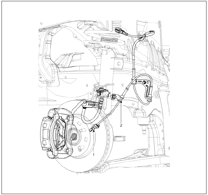
- Front wheel speed sensor
- Front wheel speed sensor cable
Front Wheel Speed Sensor Repair procedures
Removal
- Remove the tire.
Tightening torque: 107.9 - 127.5 N*m (11.0 - 13.0 kgf*m, 79.6 - 94.0 lb*ft)

Warning
Be careful not to damage the hub bolts when removing the wheel & tire.
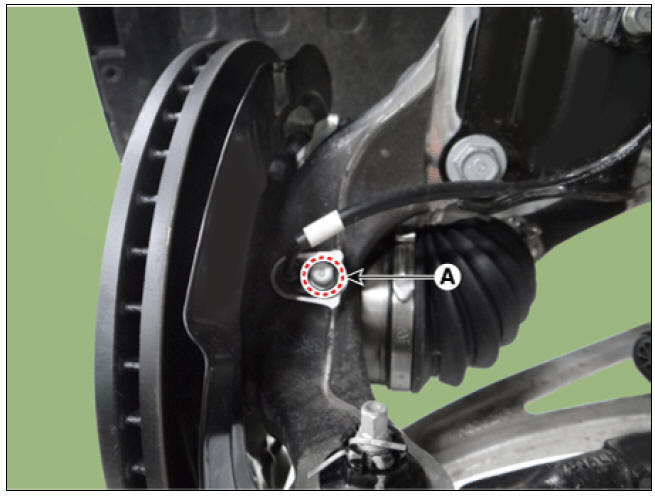
- Remove the wheel speed sensor bolt (A).
Tightening torque: 6.8 - 10.7 N*m (0.7 - 1.1 kgf*m, 5.0 - 7.9 lb*ft)
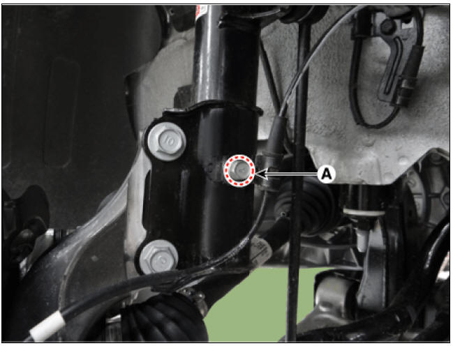
- Remove the wheel speed sensor bracket bolt (A).
Tightening torque : 8.8 - 13.7 N*m (0.9 - 1.4 kgf*m, 6.5 - 10.1 lb*ft)
- Remove the front wheel guard.
(Refer to body - "Front Wheel Guard")
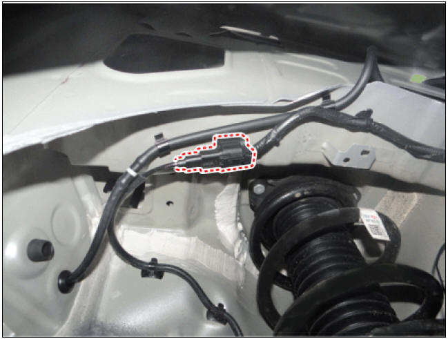
- Disconnect the front wheel speed sensor.
- Installation is the reverse of removal.
Inspection
- Measure the output voltage between the terminal of the wheel speed sensor and the body ground.
Warning
In order to protect the wheel speed sensor, when measuring output
voltage, a 100 Ω resister must be used
as shown.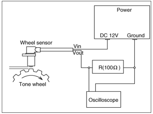
- Compare the change of the output voltage of the wheel speed sensor to
the normal change of the output
voltage as shown below.

V_low : 0.59V - 0.84V
V_high : 1.18V - 1.68V
Frequency range : 1 - 2,500Hz
READ NEXT:
 Rear wheel speed sensor
Rear wheel speed sensor
Rear Wheel Speed Sensor Components and components location
Removal
Remove the tire.
Disconnect the wheel speed sensor connector (A).
Loosen the bearing bolts (A) and then remove the hub bearing assem
 ESP OFF Switch
ESP OFF Switch Components and components location
ESP OFF swtich
Description
The ESP OFF switch is for the user to turn off the ESP system.
The ESP OFF lamp is on when ESP OFF switch is engaged.
Removal
Turn ignition switch OF
SEE MORE:
 Starting the vehicle (Kia Niro EV)
Power button
Operation
OFF
Press the EV button in P to turn the
vehicle off.
ACC (Accessory)
Press the EV button once without
depressing the brake pedal.
The steering wheel is unlocked.
The electrical accessories ca
 Energy flow
The hybrid system informs the drivers its
energy flow in various operating modes.
While driving, the current energy flow is
specified in 11 modes.
Vehicle stop
A: Idle Mode
The vehicle is stopped.
(No energy flow)
EV propulsion
A:
Categories
- Home
- KIA Niro EV, Hybrid - Second generation - (SG2) (2021-2024) - Owner's manual
- Kia Niro - First generation - (DE) (2017-2022) - Service and Repair Manual
- Contact Us
