KIA Niro: Rear wheel speed sensor
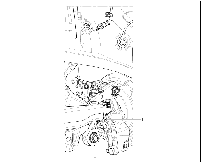
- Rear wheel speed sensor
Rear Wheel Speed Sensor Components and components location
Removal
- Remove the tire.
- Disconnect the wheel speed sensor connector (A).
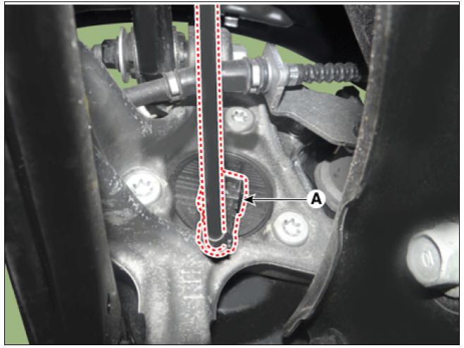
- Loosen the bearing bolts (A) and then remove the hub bearing assembly.
Tightening torque: 88.2 - 107.8 N*m (9.0 - 11.0 kgf*m, 65.0 - 79.5 lb*ft)

Inspection
- Measure the output voltage between the terminal of the wheel speed sensor and the body ground.
Warning
In order to protect the wheel speed sensor, when measuring output
voltage, a 100 Ω resister must be
used as shown. 
- Compare the change of the output voltage of the wheel speed sensor to
the normal change of the output
voltage as shown below

V_low : 0.59V - 0.84V
V_high : 1.18V - 1.68V
Frequency range : 1 - 2,500Hz
Replacement
Rear Wheel Speed Sensor
- Remove the rear wheel hub bearing assembly.
(Refer to ESP(Electronic Stability Program) System - "Rear Wheel Speed Sensor")
- Fix the rear hub bearing assembly (A) on the vise.

Warning
- When fixing on the vise, use a cloth not to be damaged the hub bearing assembly.
- Be careful if excessive force for fixing on the vise may damage the hub bearing assembly.
- Check the direction of the sensor cap (A).
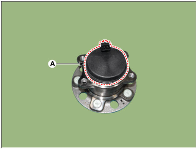
Warning
Before removing the sensor cap, check the direction of the sensor
cap connector. 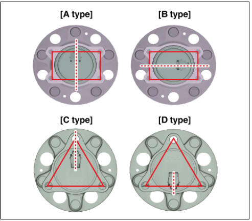
- Remove the sensor cap by hammering on a gap between sensor cap and hub bearing assembly using a scraper (A).

Warning
In order to widen the gap little by little, hammering around the
bearing cap 10-20 times. 
- When removing the sensor cap, remove it in a straight direction
not to damage the tone wheel or
encoder.

- Be careful not to damage the hub bearing assembly when using the hammer.
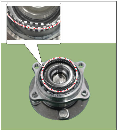
- Check if distorted or damaged the tone wheel or encoder (A).

Warning
- Check if damaged the tone wheel or encoder after removing the sensor cap and replace the hub bearing if it was deformed.
- If the tone wheel is deformed, it may arise MIL ON or other
problems.
- Position the sensor cap to the same direction of sensor cap connector (A) as you checked before removing.

Warning
Before installing the sensor cap, do not let any foreign material and contaminant into the hub bearing assembly.
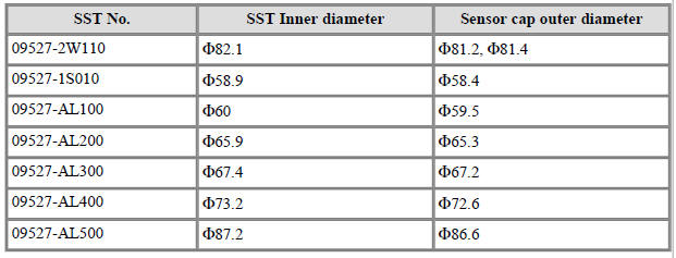
- Install the sensor cap (A) with the special service tool (09527-AL300).

Warning
- Be careful not to tilt to one side when installing the sensor cap as it may damage the tone wheel or encoder.
- When sensor cap installation, hammering it until the gap
disappeared between the sensor cap and hub
bearing assembly.

- Special Service Tools guide.
- Install the rear wheel hub bearing assembly.
(Refer to ESP(Electronic Stability Program) System - "Rear Wheel Speed Sensor")
READ NEXT:
 ESP OFF Switch
ESP OFF Switch Components and components location
ESP OFF swtich
Description
The ESP OFF switch is for the user to turn off the ESP system.
The ESP OFF lamp is on when ESP OFF switch is engaged.
Removal
Turn ignition switch OF
 Body (Interior And Exterior) - Troubleshooting
Troubleshooting
Symptom:
Water leaks from
panorama sunroof
Suspected Area → Remedy
Deteriorated roof lid
weatherstrip → Replace
Excessive roof lid-tobody
clearance and
improperly fitted
weatherstrip → Adjust
Sympto
SEE MORE:
 Seat belts
Seat belts are designed to bear upon the
bony structure of the body, and should
be worn low across the front of the pelvis,
chest and shoulders.
WARNING
For maximum restraint system protection,
the seat belts must always be
used whenever
 Overhead Console Lamp Repair procedures | Hazard Lamp Switch
Inspection
Remove the overhead console lamp.
(Refer to Lighting System - "Overhead Console Lamp")
Check for continuity between terminals.
Removal
Disconnect the negative (-) battery terminal.
Remove
Categories
- Home
- KIA Niro EV, Hybrid - Second generation - (SG2) (2021-2024) - Owner's manual
- Kia Niro - First generation - (DE) (2017-2022) - Service and Repair Manual
- Contact Us
