KIA Niro: External AMP | Roof Antenna | AVN Remote Controller
Kia Niro - First generation - (DE) (2017-2022) - Service and Repair Manual / Body Electrical System / AVN System / External AMP | Roof Antenna | AVN Remote Controller

Connector Pin Information

External AMP Repair procedures
Removal
- Remove the main crash pad.
(Refer to Body - "Main Crash Pad Assembly")
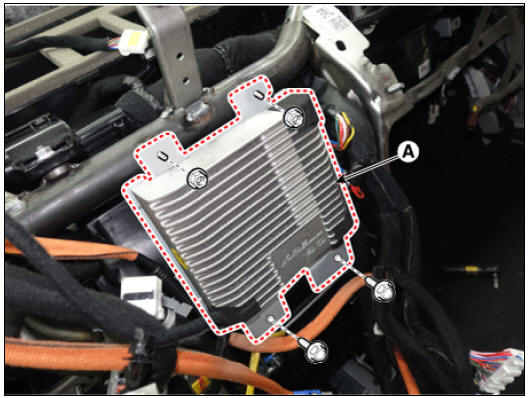
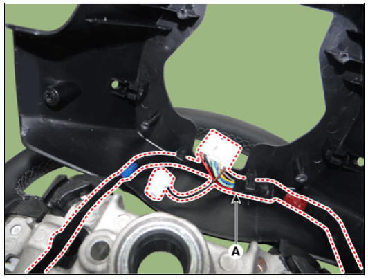
- Remove the external amplifier (A) after loosening the mounting bolts and nuts.
- Disconnect the connectors (A) from the external amplifier.

Installation
- Install in the reverse order of removal.
Roof Antenna
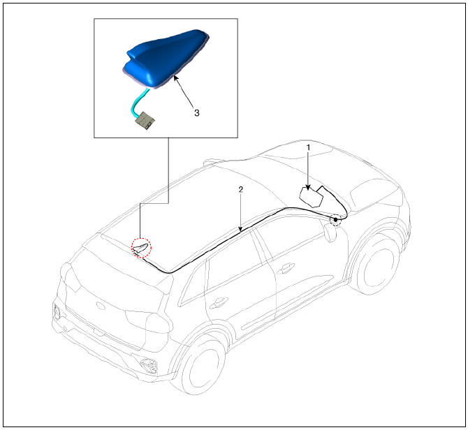
- Audio/AVN head unit
- Antenna feeder cable
- Roof antenna
Removal
Roof antenna
- Disconnect the negative (-) battery terminal.
- Remove the roof trim assembly.
(Refer to Body - "Roof Trim Assembly")
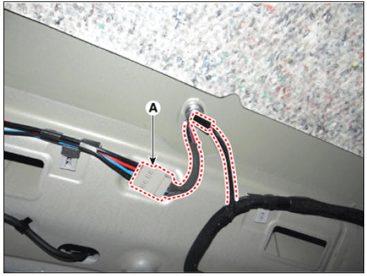
- Disconnect the roof antenna cable and connectors (A).
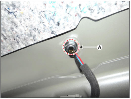
- Remove the roof antenna (B) after loosening a nut (A).

Installation
- Install in the reverse order of removal.
AVN Remote Controller
- Left Remote Control Switch (Audio + Hands free + Voice)
- Right Remote Control Switch (Cruise+Trip Computer)
Circuit Diagram

Audio + Bluetooth

Audio + Bluetooth + Voice

Trip

Trip + Cruise

Trip + Cruise + SCC

(Trip + Cruise + SLD) (Europe Only)

(Trip + SCC + SLD) (Europe Only)

AVN Remote Controller Repair procedures
Removal
- Disconnect the negative (-) battery terminal.
- Remove the steering wheel assembly.
(Refer to Steering System - "Steering Wheel")
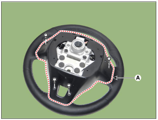
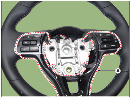
- Remove the steering back cover (A) after loosening the mounting screws.
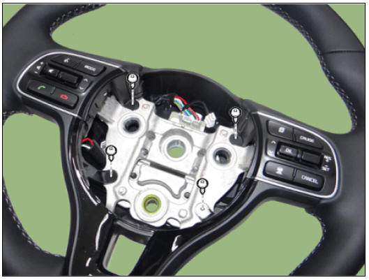
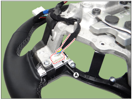
- Remove the wiring connector (A) from the steering back cover.
- Disconnect the steering wheel remote control connector (A).
LH

RH
- Remove the steering wheel remote control assembly (A) after loosening the mounting screws.
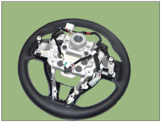
- Remove the steering wheel remote control (A) after loosening the mounting screws.
LH

RH

Installation
- Install in the reverse order of removal.
Inspection
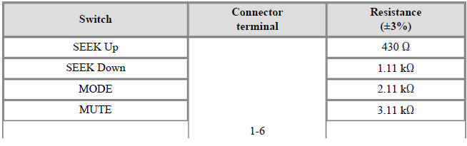
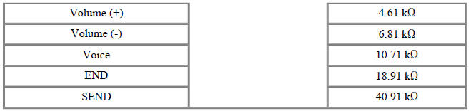
- Check for resistance between terminals in each switch position (LH).
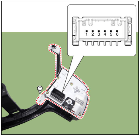
LH : Audio + Hands free + Voice
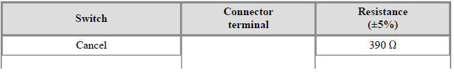
- Check for resistance between terminals in each switch position (RH).

RH : Cruise + Trip

READ NEXT:
 Multimedia Jack
Circuit Diagram
Description
The multimedia jack on the console upper cover is for customers who like to
listen to external portable music players like the
MP3 etc., through the vehicle's sound system when it is linked to this jack. The
SEE MORE:
Lighting controls (Kia NIRO Hybrid)
Operating lights
Type A
Type B
Type C
Operation
/
Tailamps and headlamps will turn
ON or OFF automatically depending
on the amount of light outside
the vehicle.
Position & Taillamp ( )
Low beam
Safe use of the Tire Mobility Kit
Stop the vehicle in a safe, level place
away from traffic.
Set the parking brake.
Only use the Tire Mobility Kit for sealing/
inflating passenger vehicle tires.
Do not remove any foreign objects
from the tire.
Read the precautionary
Categories
- Home
- KIA Niro EV, Hybrid - Second generation - (SG2) (2021-2024) - Owner's manual
- Kia Niro - First generation - (DE) (2017-2022) - Service and Repair Manual
- Contact Us