KIA Niro: Engine Clutch System
Specifications
Clutch Cover and Disc

Engine Clutch Actuator

Service Standard

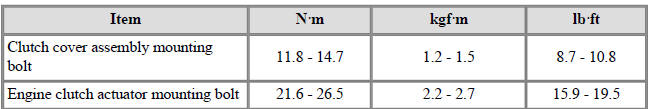
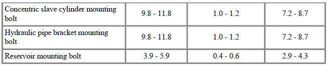
Tightening Torques
Lubricants

Special Service Tools

Tool Name /
Number/
Illustration / Description
Clutch disc
guide
09411-1P000/ 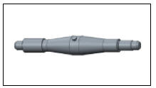 /Used for fixing
clutch disc assembly
/Used for fixing
clutch disc assembly
when installing
clutch cover
assembly.
Used with the
adapter (09411-
G2100)
Adapter
09411-G2100/  / Used for fixing
clutch disc assembly
/ Used for fixing
clutch disc assembly
when installing
clutch cover
assembly.
Used with the clutch
disc guide (09411-
1P000)
Removal
- Remove the engine clutch reservoir cap (A).

Warning
If use the engine clutch fluid syringe.
- Drain the engine clutch fluid from the reservoir using a syringe.
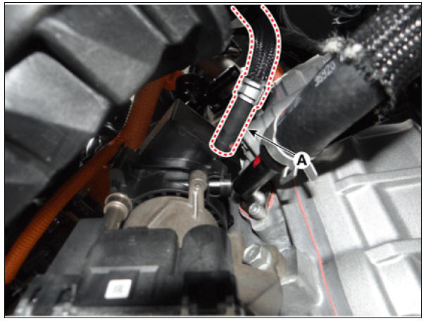
If do not use the engine clutch fluid syringe.
1) Remove the engine under cover.
(Refer to Engine Mechanical System - "Engine Room Under Cover")
2) Drain the engine clutch fluid after remove the engine clutch fluid hose (A).
Warning
Do not spill brake fluid on the vehicle, it may damage the paint. if brake fluid does contact the paint, wash it off immediately with water.
Installation
- Install in the reverse order of removal.
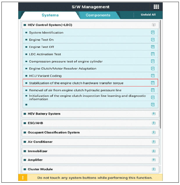
- Operate by using KDS as in the order below after filling regulation hydraulic fluid in reservoir.
Specified hydraulic fluid : Brake fluid DOT 3 Quantity : Fill the hydraulic fluid to the reservoir so that it comes between the MAX and MIN levels of the reservoir.
(1) Perform initialization of the engine clutch inspection line learning and diagnostic information.

(2) Bleed the air from engine clutch hydraulic pressure line.
Warning
Be sure to bleed air from the engine clutch hydraulic pressure line at outside temperature between 0 - 40ºC (32 - 104ºF). If not, the air bleeding would be not done well.

Warning
Refil the hydraulic fluid to MAX-MIN level, if the fluid is lower than MIN level while performing the air bleeding.
(3) Perform engine clutch/motor resolver adaptation.

(4) Perform stabilization of the engine clutch hardware transfer torque.
- Engine Clutch Actuator
- Concentric Slave Cylinder Assembly Repair procedures
- Clutch Cover And Disc Repair procedures
- Reservoir Repair procedures
READ NEXT:
 Engine Clutch Actuator
Components
Clutch disc
Clutch cover
Concentric slave cylinder
Hybrid motor assembly
Engine clutch actuator
Reservoir
Specifications
Schematic Diagrams
Harness Connector
Engine Clutch Actuator Repair procedu
Concentric Slave Cylinder Assembly Repair procedures
Removal
Remove the hybrid motor assembly.
(Refer to Hybrid Motor System - "Hybrid Motor Assembly")
Remove the engine clutch actuator.
(Refer to Engine Clutch System - "Engine Clutch Actuator")
Remove the adapter (A
Clutch Cover And Disc Repair procedures
Removal
Remove the hybrid motor assembly.
(Refer to Hybrid Motor System - "Hybrid Motor Assembly")
Remove the clutch cover assembly and clutch disc after loosening the
bolts.
Warning
Be careful not to be bent or twist b
SEE MORE:
AHB Brake System Bleeding procedure
The iBAU consists of 3 brake fluid lines in total (Low/high pressure and
pedal simulator lines), therefore, air bleeding should be made
sequentially following the procedure below.
Bleeding sequence : Low pressure/Pedal simulator section (
High voltage battery warmer system
The high voltage battery warmer system
prevents reduction of battery output
when battery temperature is low. If the
charging connector is connected, the
warmer system automatically operates
according to the battery temperature.
Charging time
Categories
- Home
- KIA Niro EV, Hybrid - Second generation - (SG2) (2021-2024) - Owner's manual
- Kia Niro - First generation - (DE) (2017-2022) - Service and Repair Manual
- Contact Us