KIA Niro: Cooling Fan Repair procedures | Cooling Fan Assembly
Kia Niro - First generation - (DE) (2017-2022) - Service and Repair Manual / Engine Mechanical System / Cooling System / Cooling Fan Repair procedures | Cooling Fan Assembly
Cooling Fan Components and components location
Components
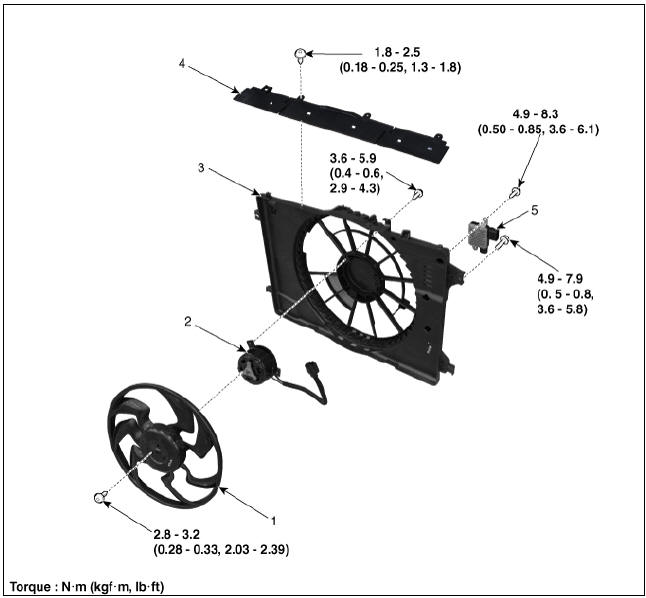
- Cooling fan
- Cooling fan motor
- Cooling fan shroud
- Air dam
- Cooling fan controller (PWM)
Description
Controls the cooling fan motor voltage depending on the duty output from the ECU (Freq.: 300Hz).
Signal from the ECU to the PWM (SI: 300Hz)
Specifications

Circuit Diagram
PWM Circuit Diagram

Cooling Fan Assembly
Removal and
Installation
- Disconnect the negative battery terminal.
- Remove the air cleaner and air duct A.
(Refer to Intake and Exhaust System - "Air Cleaner")
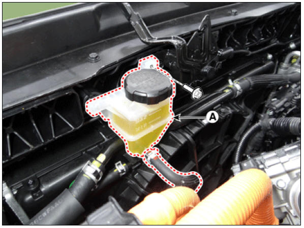
- Separate the engine clutch reservoir tank (A).
Tightening torque : 3.9 - 5.9 N*m (0.4 - 0.6 kgf*m, 2.9 - 4.3 lb*ft)
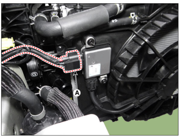
- Disconnect the cooling fan control module (PWM) connector (A).
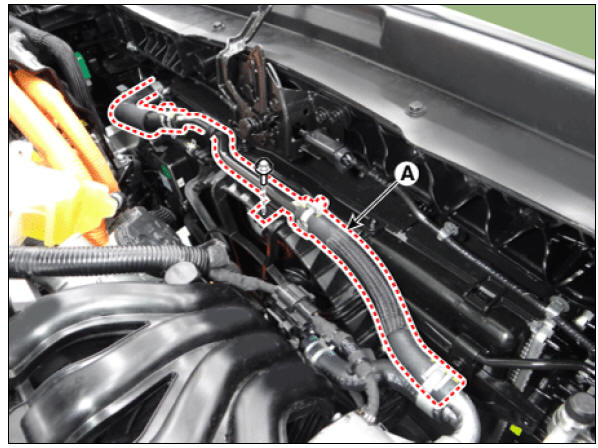
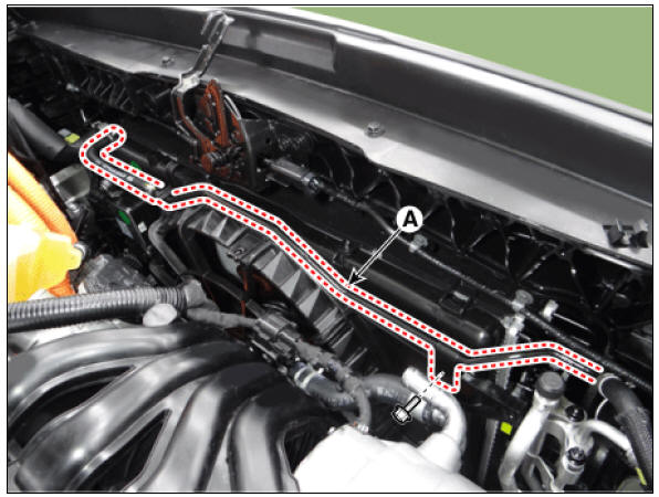
- Remove the hybrid starter generator coolant hose & pipe (A) from the cooling fan shroud.
Tightening torque : 7.8 - 11.8 N*m (0.8 - 1.2 kgf*m, 5.8 - 8.7 lb*ft)
- Separate the radiator coolant pipe (A) from the cooling fan shroud.
Tightening torque : 7.8 - 11.8 N*m (0.8 - 1.2 kgf*m, 5.8 - 8.7 lb*ft)
- Remove the air dam (A).
Tightening torque : 1.8 - 2.5 N*m (0.18 - 0.25 kgf*m, 1.3 - 1.8 lb*ft)
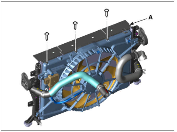
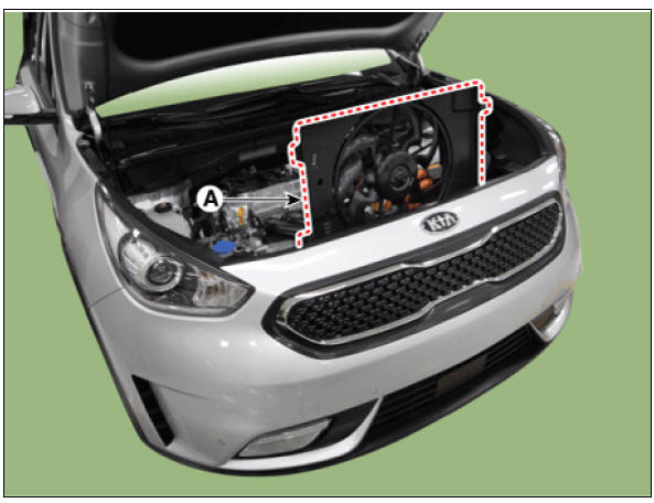
- Remove the cooling fan assembly (A).
Tightening torque : 4.9 - 8.3 N*m (0.5 - 0.8 kgf*m, 3.6 - 6.1 lb*ft)
- Install in the reverse order of removal.
READ NEXT:
 Cooling Fan Control Module (PWM) | Radiator
Disconnect the battery negative terminal.
Remove the air duct.
(Refer to Intake and Exhaust System - "Air Cleaner")
Disconnect the cooling fan control module (PWM) connector (A) and cooling fan motor
SEE MORE:
How to connect
Outdoor (if equipped)
Open the cover of the V2L connector.
Close the cover after connecting
home appliances and electronic products
to the power outlet.
Connect the V2L connector to the
charging hole on the vehicle.
Pr
Engine Mechanical System / Troubleshooting
Symptoms :
Engine misfire with abnormal internal lower engine noises
Suspected area ‚†’ Remedy
Worn crankshaft bearings ‚†’ Replace the crankshaft and bearings as requ
Categories
- Home
- KIA Niro EV, Hybrid - Second generation - (SG2) (2021-2024) - Owner's manual
- Kia Niro - First generation - (DE) (2017-2022) - Service and Repair Manual
- Contact Us