KIA Niro: Cooling Fan Control Module (PWM) | Radiator
- Disconnect the battery negative terminal.
- Remove the air duct.
(Refer to Intake and Exhaust System - "Air Cleaner")
- Disconnect the cooling fan control module (PWM) connector (A) and cooling fan motor connector (B).
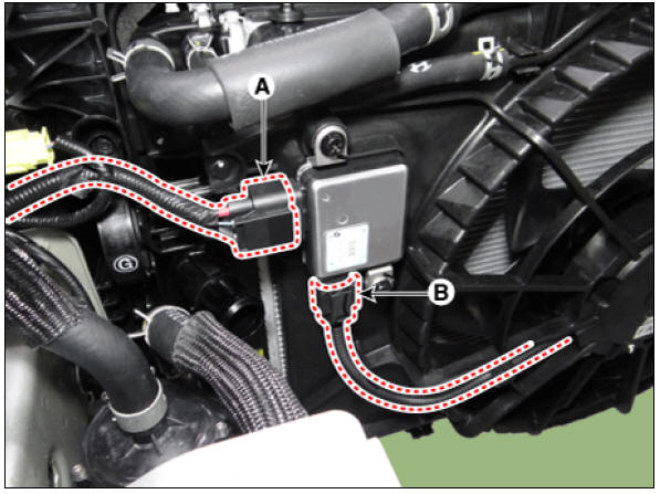
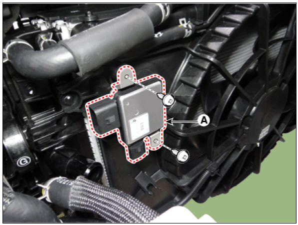
- Remove the cooling fan control module (PWM) (A).
Tightening torque : 4.9 - 8.3 N*m (0.50 - 0.85 kgf*m, 3.6 - 6.1 lb*ft)
- Install in the reverse order of removal.
Disassembly
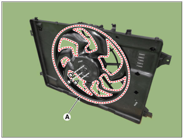
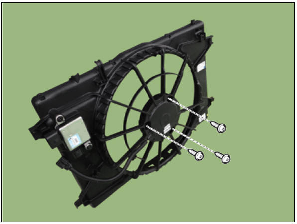
- Remove the cooling fan (A) from cooling fan shroud.
Tightening torque : 2.8 - 3.2 N*m (0.28 - 0.33 kgf*m, 2.0 - 2.4 lb*ft)
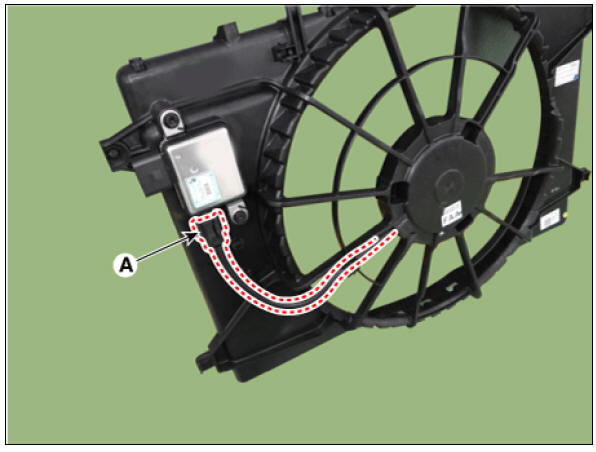
- Disconnect the cooling fan motor connector (A).
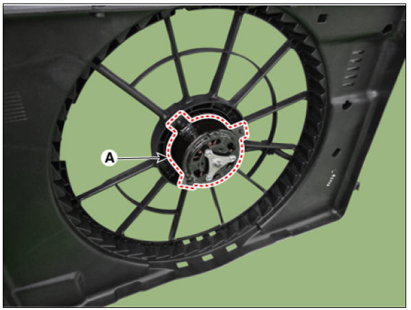
- Remove the cooling fan motor (A) from cooling fan shroud.
Tightening torque : 3.9 - 5.9 N*m (0.4 - 0.6 kgf*m, 2.9 - 4.3 lb*ft)
- Install in the reverse order of removal.
Inspection
Fan Motor
- Disconnect the fan motor connector from the resistor.
- Connect the battery voltage to the "+" terminal and ground to " - " terminal.
- Check the cooling fan motor operates well.
Radiator
Components
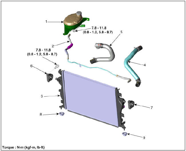
- Reservoir tank
- Radiator reservoir hose & pipe
- Radiator
- Radiator upper hose
- Radiator lower hose
- Radiator upper bracket (RH)
- Radiator upper bracket (LH)
- Radiator lower mounting insulator (RH)
- Radiator lower mounting insulator (LH)
Radiator Repair procedures
Removal and Installation
- Disconnect the negative battery terminal.
- Remove the air cleaner.
(Refer to Intake and Exhaust System - "Air Cleaner")
- Remove the engine room under cover.
(Refer to Engine and Transaxle Assembly - "Engine Room Under Cover")
- Drain the coolant.
(Refer to Cooling System - "Coolant")
- Remove the cooling fan assembly.
(Refer to Cooling System - "Cooling Fan")
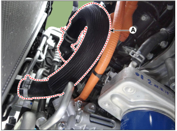
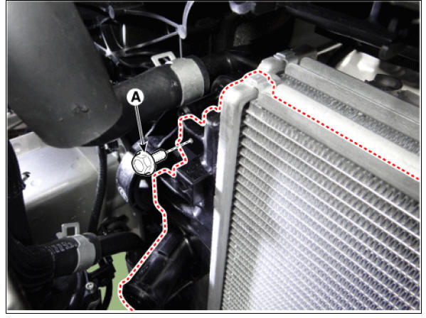
- Disconnect the radiator upper hose (A) from the radiator.
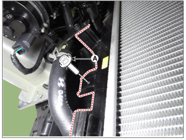
- Disconnect the radiator lower hose (A) from the radiator.
- Disconnect the radiator reservoir hose (A).
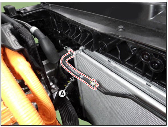
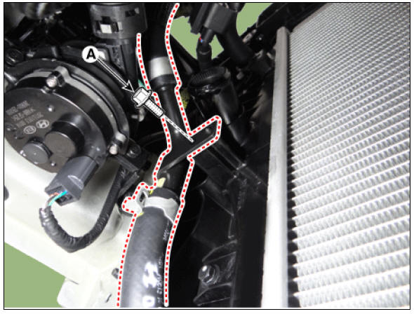
- Separate the A/C pipe (A) from the radiator.
Tightening torque : 4.9 - 8.3 N*m (0.5 - 0.8 kgf*m, 3.6 - 6.1 lb*ft)
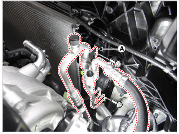
- Remove the radiator upper mounting bracket (A).
Tightening torque : 7.8 - 11.8 N*m (0.8 - 1.2 kgf*m, 5.8 - 8.7 lb*ft)
- Remove the radiator upper mounting bolt (A).
Tightening torque : 4.9 - 8.3 N*m (0.5 - 0.8 kgf*m, 3.6 - 6.1 lb*ft)
RH

LH
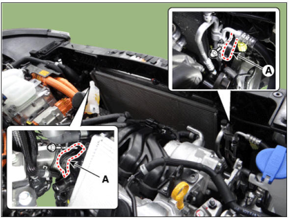
- Remove the radiator lower mounting bolt (A).
Tightening torque : 4.9 - 8.3 N*m (0.5 - 0.8 kgf*m, 3.6 - 6.1 lb*ft)
RH

LH
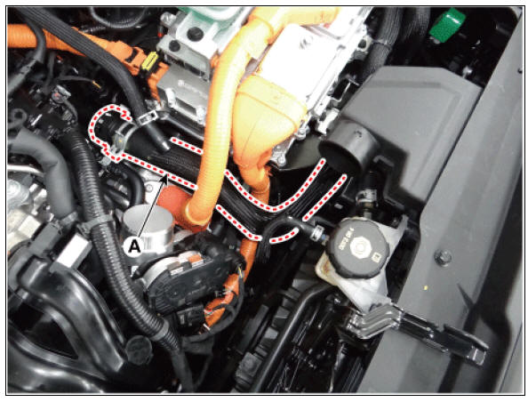
- Remove the inverter radiator lower pipe (A) from the radiator.
Tightening torque : 7.8 - 11.8 N*m (0.8 - 1.2 kgf*m, 5.8 - 8.7 lb*ft)
- Remove the radiator (A).
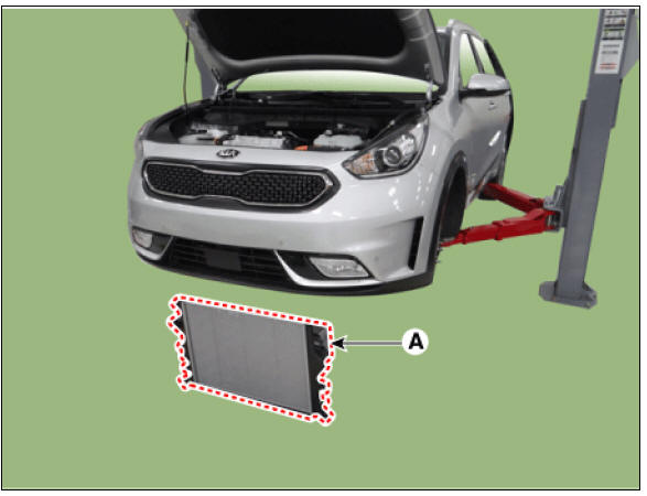
- Install in the reverse order of removal.
- Fill the radiator with coolant and check for leaks.
Inspection
Pressure Cap Testing
- Install the pressure cap and pressure tester on a SST (0K253-G5100).
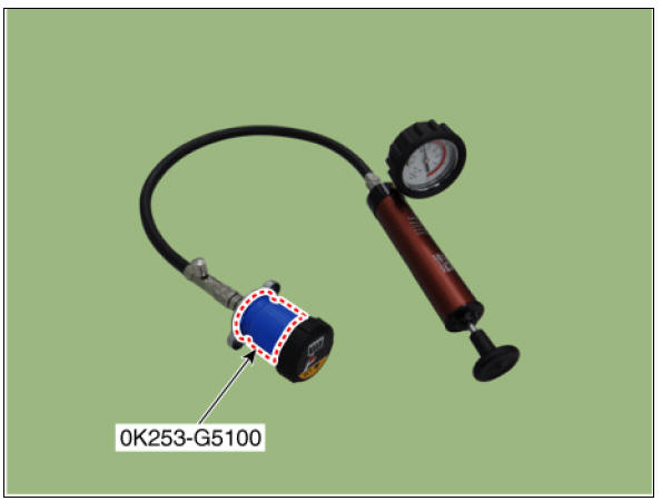
- Apply a pressure of 79.4 - 122.58 kPa (0.95 - 1.25 kgf/cm², 11.5 - 17.78 psi).
- Check for a drop in pressure.
- If the pressure drops, replace the pressure cap.
Radiator Leakage Test
- Wait until engine is cool, then carefully remove the pressure cap and fill the reservoir tank with engine coolant, then install it on the pressure tester.

- Apply a pressure tester to the radiator and apply a pressure of 93.16 - 122.58 kPa (0.95 - 1.25 kgf/cm², 13.51 - 17.78 psi).
- Inspect for engine coolant leaks and a drop in pressure.
- Remove the tester and reinstall the pressure cap.
Warning
Check for engine oil in coolant and/or coolant in engine oil.
Removal and Installation
- Drain the coolant.
(Refer to Cooling System - "Coolant")
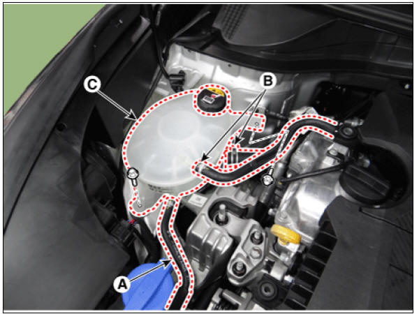
- Disconnect the radiator reservoir hose (A).
- Disconnect the reservoir hose (B).
- Remove the reservoir tank (C).
Tightening torque : 7.8 - 11.8 N*m (0.8 - 1.2 kgf*m, 5.8 - 8.7 lb*ft)
- Install in the reverse order of removal.
- Fill the coolant.
(Refer to Cooling System - "Coolant")
READ NEXT:
 Water pump Repair procedures
Removal
Warning
Be sure to read and follow the "General Safety Information and
Caution" before doing any work related
with the high voltage system. Failure to follow the safety instructions may
result in serious electrical
injuries.
Thermostat Repair procedures
Removal and
Installation
Warning
Disassembly of the thermostat may have an adverse effect, causing
deteriorated cooling efficiency. Do not
remove the thermostat, even if the engine tends to overheat.
Remove the engine room under cover.
(R
SEE MORE:
Power windows automatic reversal
Kia NIRO Hybrid
Operation
Windows will stop and move down.
Approximately 30 cm (12 inches)
Windows will move down.
Approximately 2.5 cm (1 inch)
Operating condition(s)
WARNING
Always check for obstructions before
rais
Battery conditioning mode (if equipped)
A: EV Settings
Battery conditioning mode
Battery conditioning mode
The Battery conditioning mode is efficient
during the winter time when the
high voltage battery temperature is
low. This mode is recommended to
improve driving
Categories
- Home
- KIA Niro EV, Hybrid - Second generation - (SG2) (2021-2024) - Owner's manual
- Kia Niro - First generation - (DE) (2017-2022) - Service and Repair Manual
- Contact Us