KIA Niro: Brake Pedal
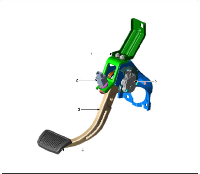
- Brake pedal member assembly
- Stop lamp switch
- Brake pedal arm
- Brake pedal pad
- Brake pedal stroke sensor
Removal
- Turn ignition switch OFF and disconnect the negative (-) battery terminal.
- Remove the crash pad lower panel.
(Refer to Body - "Crash Pad")
- Remove the knee air bag.
(Refer to Restraint - "Knee Airbag(KAB) Module")
- Remove the Steering column and shaft.
(Refer to the Steering System - "Steering Columm and Shaft")
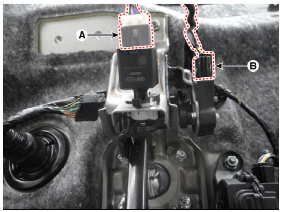
- Disconnect the stop lamp switch (A) and brake pedal stroke sensor connector (B).
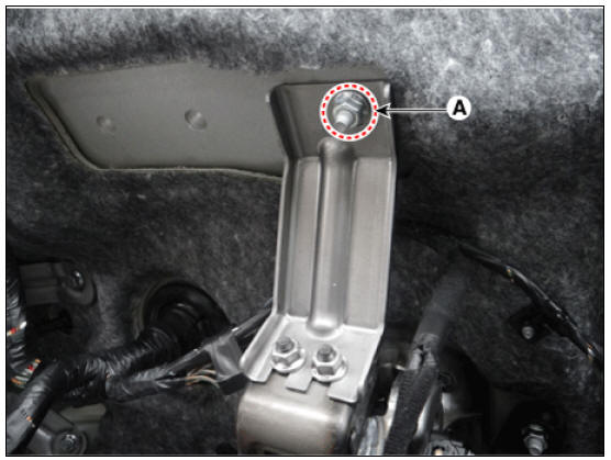
- Loosen the nut (A) and then remove the bracket.
Tightening torque : 16.6 - 25.4 N*m (1.7 - 2.6 kgf*m, 12.2 - 18.8 lb*ft)
- Remove the snap pin (A) and clebis pin (B).
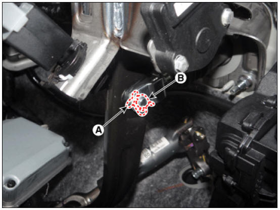
- Loosen the brake pedal nuts and then remove the brake pedal.
Tightening torque : 16.6 - 25.4 N*m (1.7 - 2.6 kgf*m, 12.2 - 18.8 lb*ft)

Installation
- Installation is the reverse of removal.
- Check the brake pedal operation.
- Conduct the pedal traval sensor (PTS) calibration.
Diagnostic Procedure Using a Diagnostic Instrument
Brake Pedal Sensor Calibration
The brake pedal sensor calculates the pedal full stroke according to the preset zero. Therefore, zeroing adjustment is necessary when first installed.Calibration must be performed as following cases.
- After changing the brake pedal assembly (you cannot change only the sensor).
- After changing the IEB (Integrated lectronic Booster).
- When error codes C1380 (calibration) or C1379 (signal error) are detected.
- After bleeding IEB line.
Brake Pedal Travel Sensor (PTS) Calibration Procedure
The calibration must be done while the vehicle is parked without stepping on the brake pedal and while there is no vibration on the vehicle.
- Connect self-diagnosis connector (16pins) located under the driver side crash pad to self-diagnosis device, and then turn the selfdiagnosis device after key is ON.
- Select the "vehicle model" and "ESC/AHB" on KDS vehicle selection screen.
- Proceed with the test according to the screen instructions.

READ NEXT:
 Front Disc Brake
Front Disc Brake Components and components location
Bleed screw
Caliper body
Pad inner shim
Brake pad
Pad return spring
Caliper carrier
Pad retainer
Removal
Remove the wheel & tire.
Remove the caliper hose bracket bol
Rear Disc Brake
With EPB
Brake pad
Pad return spring
Caliper carrier
Pad retainer
Caliper body
Lever return spring
Stopper
Operating lever
Bleed screw
EPB actuator
Bleed screw
Caliper body
Caliper carrier
Pad retainer
Brake
Stop Lamp Switch
Stop Lamp Switch Components and components location
Brake pedal member assembly
Stop lamp switch
Brake pedal arm
Brake pedal pad
Brake pedal stroke sensor
Operation
Operation principle of inductive non-contact switch
Use the
SEE MORE:
Tire specification and pressure label
Type A
Type B
The tire label located on the center pillar
as shown gives the tire pressures recommended
for your vehicle. The tires supplied
on your new vehicle are chosen to
provide the best performance for normal
driving.
Motor number (
Active air flap
Active air flap system controls the air
flap below the front bumper to cool the
vehicle parts and improve energy efficiency.
Active air flap malfunction
A: Check Active Air Flap System
The active air flap system may not operate
normally
Categories
- Home
- KIA Niro EV, Hybrid - Second generation - (SG2) (2021-2024) - Owner's manual
- Kia Niro - First generation - (DE) (2017-2022) - Service and Repair Manual
- Contact Us