KIA Niro: Rear Disc Brake
With EPB
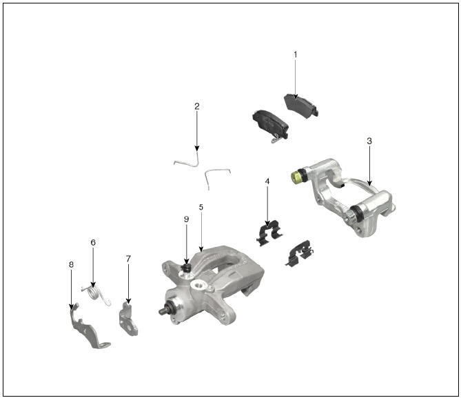
- Brake pad
- Pad return spring
- Caliper carrier
- Pad retainer
- Caliper body
- Lever return spring
- Stopper
- Operating lever
- Bleed screw
- EPB actuator
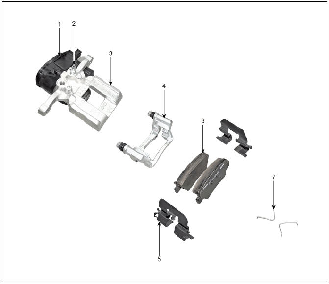
- Bleed screw
- Caliper body
- Caliper carrier
- Pad retainer
- Brake pad
- Pad return spring
Removal
With EPB
- Release the EPB, push the EPB switch.
- Turn ignition switch OFF and disconnect the negative (-) battery terminal.
- Remove the rear wheel and tire.
Tightening torque: 107.9 - 127.5 N*m (11.0 - 13.0 kgf*m, 79.6 - 94.0 lb*ft)
Warning
Be careful not to damage to the hub bolts when removing the front wheel and tire.
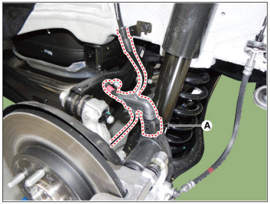
- Disconnect the EPB actuator connector (A).
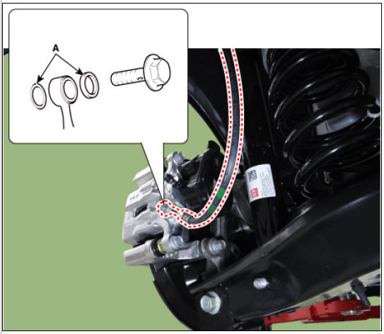
- Disconnect the brake hose (A) from the brake caliper by loosening the bolt.
Tightening torque : 24.5 - 29.4 N*m (2.5 - 3.0 kgf*m, 18.1 - 21.7 lb*ft)

Warning
Use a new washers (A) whenever installing.
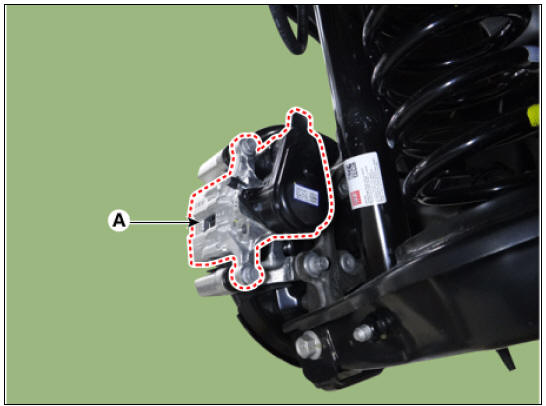
- Loosen the guide rod bolts, and then remove the caliper body (A).
Tightening torque: 21.6 - 31.4 N*m (2.2 - 3.2 kgf*m, 15.9 - 23.1 lb*ft)
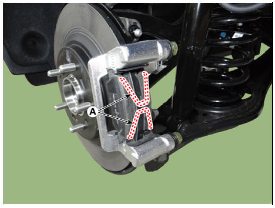
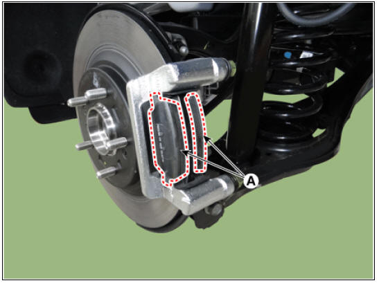
- Remove the pad return springs (A).
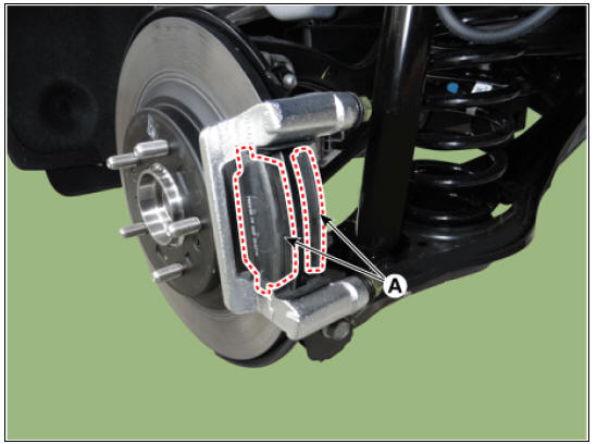
- Remove the brake pads (A).
- Remove the pad liner (A).

Warning
Place the return spring, pad liner, inner brake shim, and brake pad all at the same time when replacing the brake pad.
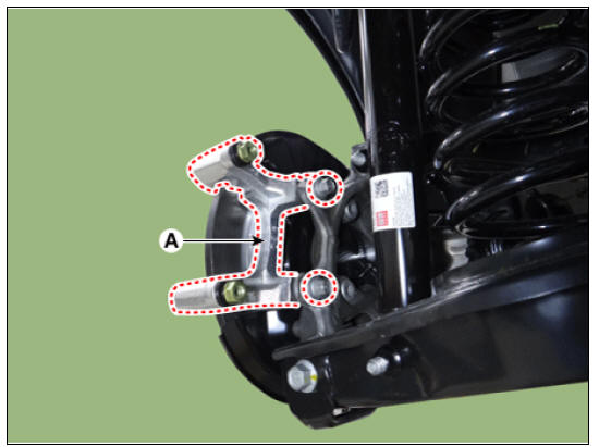
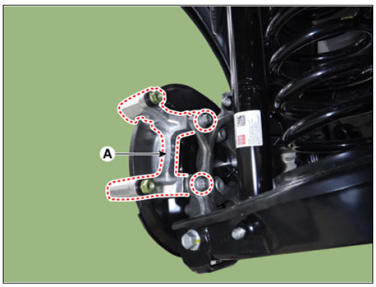
- Remove the brake caliper carrier (A) by loosening the bolts.
Tightening torque : EPB : 78.4 - 98.0 N*m (8.0 - 10.0 kgf*m, 57.8 - 72.3 lb*ft) Non-EPB : 63.5 - 73.5 N*m (6.5 - 7.5 kgf*m, 47.0 - 54.2 lb*ft)
- Loosen the screw and then remove the brake disk (A).
Tightening torque : 4.9 - 5.8 N*m (0.5 - 0.6 kgf*m, 3.6 - 4.3 Ib*ft)

Without EPB
- Release the parking brake lever and parking brake cable is loose.
- Remove the rear wheel and tire.
Tightening torque: 107.9 - 127.5 N*m (11.0 - 13.0 kgf*m, 79.6 - 94.0 lb*ft)
Warning
Be careful not to damage to the hub bolts when removing the front wheel and tire.
- Remove the parking brake cable pin (A).
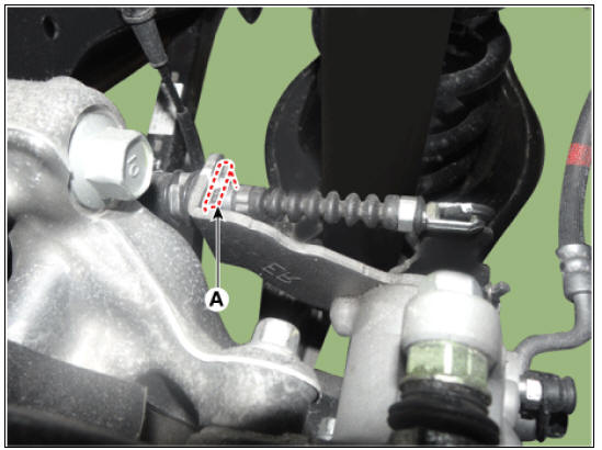
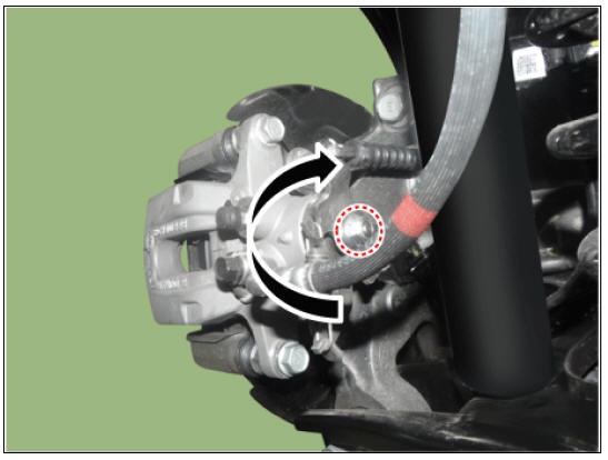
- Rotates the nut in the clockwise direction and then remove the parking cable.
- Disconnect the brake hose (A) from the brake caliper by loosening the bolt.
Tightening torque : 24.5 - 29.4 N*m (2.5 - 3.0 kgf*m, 18.1 - 21.7 lb*ft)

Warning
Use a new washers (A) whenever installing.

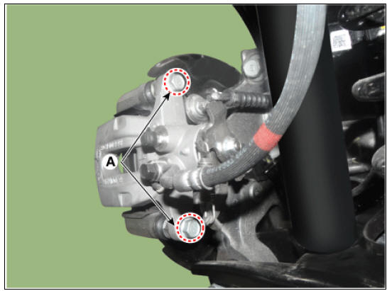
- Loosen the guide rod bolts (A), and then remove the caliper body.
- Remove the pad return spring (A)
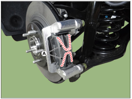
- Remove the brake pads (A).
- Remove the pad liner (A).

Warning
Place the return spring, pad liner, inner brake shim, and brake pad all at the same time when replacing the brake pad.
- Remove the brake caliper carrier (A) by loosening the bolts.
Tightening torque :
EPB : 78.4 - 98.0 N*m (8.0 - 10.0 kgf*m, 57.8 - 72.3 lb*ft)
Non-EPB : 63.5 - 73.5 N*m (6.5 - 7.5 kgf*m, 47.0 - 54.2 lb*ft)
- Loosen the screw and then remove the brake disk (A).
Tightening torque : 4.9 - 5.8 N*m (0.5 - 0.6 kgf*m, 3.6 - 4.3 Ib*ft)

Inspection
Rear Brake Disc Thickness Check
- Check the brake pads for wear and fade.
- Check the brake disc for damage and cracks.
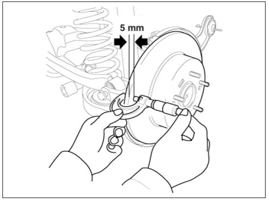
- Remove all rust and contamination from the surface, and measure the disc thickness at 8 points, at least, of same distance (5mm) from the brake disc outer circle.
Brake disc thickness
Standard: 10 mm (0.39 in)
Service limit: 8.4 mm (0.33 in)
Deviation: less than 0.01 mm (0.0004 in)
- If wear exceeds the limit, replace the discs and pad assembly left and right of the vehicle.
Rear Brake Pad Check
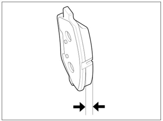
- Check the pad wear. Measure the pad thickness and replace it, if it is less than the specified value.
Pad thickness
Standard value: 10.0 mm (0.3937 in.)
Service limit: 2.0 mm (0.0787 in.)
- Check that grease is applied, to sliding contact points. Check for metal damage to the pad and backing.
Rear Brake Disc Runout Check
- Place a dial gauge about 5mm (0.2 in.) from the outer circumference of the brake disc, and measure the runout of the disc.
Brake disc runout
Limit: 0.05 mm (0.002 in.) or less (new one)
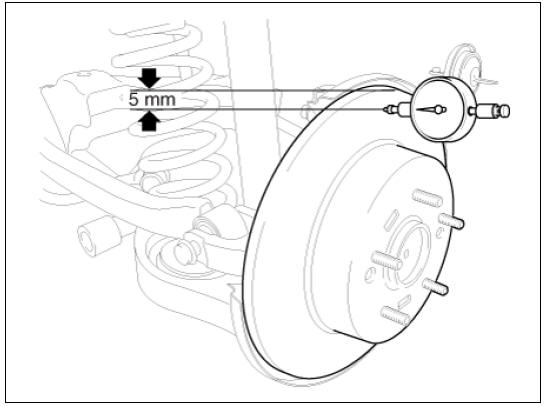
- If the runout of the brake disc exceeds the limit specification, replace the disc, and then measure the runout again.
- If the runout does not meet the limit specification, remove the disc, turn it 180º and reinstall. Then check the runout of the brake disc again.
- If the runout cannot be corrected by changing the position of the brake disc, replace the brake disc.
Installation
- Installation is the reverse of removal.
Warning
With EPB
When installing, press and rotate the piston into the caliper body until it is fully retracted.
Without EPB
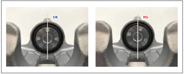
- Rotate the caliper piston clockwise by using a SST
(09580-0U000).

- Check the groove position.
- After filling the brake fluid in the reservoir, perform the air bleed.
(Refer to the Brake system - "Brake Bleeding Procedure")
Warning
- For the brake pad to locate on the normal operation position, depress the brake pedal halfway several times until the brake pedal gains resistance.
- After disassembling/assembling the caliper body or replacing the brake caliper, parking brake cable or brake disc, re-adjust the parking brake.
READ NEXT:
 Stop Lamp Switch
Stop Lamp Switch Components and components location
Brake pedal member assembly
Stop lamp switch
Brake pedal arm
Brake pedal pad
Brake pedal stroke sensor
Operation
Operation principle of inductive non-contact switch
Use the
Stop Lamp Switch Repair procedures
Removal
Turn ignition switch OFF and disconnect the negative (-) battery
terminal.
Remove the crash pad lower panel.
(Refer to Body - "Crash Pad")
Remove the knee air bag.
(Refer to Restraint - "Knee Airbag(KAB) Module&q
SEE MORE:
Replacing rear wiper blade Kia Niro EV / Hybrid
Replacing rear wiper blade
Operation
Turn off the vehicle.
Move the wiper switch to the single
wiping (MIST/1x) position.
Hold the wiper switch for more than 2
seconds.
Raise the wiper arm and pull out the
wiper blade assembly.
Fuel Pressure Control Valve (FPCV)
Specification
Fuel Pressure Control Valve (FPCV) Description
Description
Installed on the high pressure fuel pump, the Fuel Pressure Control Valve
controls the flow of fuel into
the injectors in accordance with the ECM signal calculated ba
Categories
- Home
- KIA Niro EV, Hybrid - Second generation - (SG2) (2021-2024) - Owner's manual
- Kia Niro - First generation - (DE) (2017-2022) - Service and Repair Manual
- Contact Us