KIA Niro: Brake Actuation Unit Repair procedures
Brake Actuation Unit Components and components location
Components

Warning
IBAU(Intergrated Brake Actuation Unit) must not be disassembled.
- Integrated Brake Actuation Unit (IBAU) ECU
- Reservoir
- Pedal Simulator
- Integrated Brake Actuation Unit (IBAU)
Brake Actuation Unit Repair procedures
Removal
Warning
The following section describes how to diagnose faults using a diagnostic instrument.
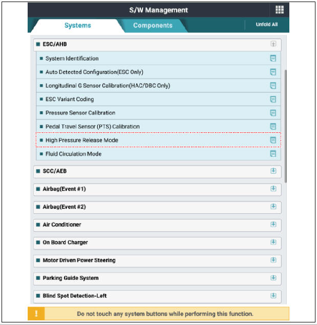
1) Connect self-diagnosis connector (16pins) located under the driver side crash pad to self-diagnosis device, and then turn the self-diagnosis device after key is ON.
2) Select the "vehicle model" and "ESC/AHB" on KDS vehicle selection screen.
3) Select the "High Pressure Release Mode" on KDS screen, then select OK.
4) Proceed with the test according to the screen instructions.
- Turn ignition switch OFF and disconnect the negative (-) battery terminal.
- Disconnect the ECM & TCM bracket.
(Refer to Engine Control System - "Engine Control Module (ECM)")
- Remove the air cleaner assembly.
(Refer to Engine Mechanical System - "Air Cleaner")
- Remove the brake fluid from the master cylinder reservoir with a syringe.
Warning
Do not spill brake fluid on the vehicle as it may damage the paint. If brake fluid comes in contact with the paint, wash off immediately with water.
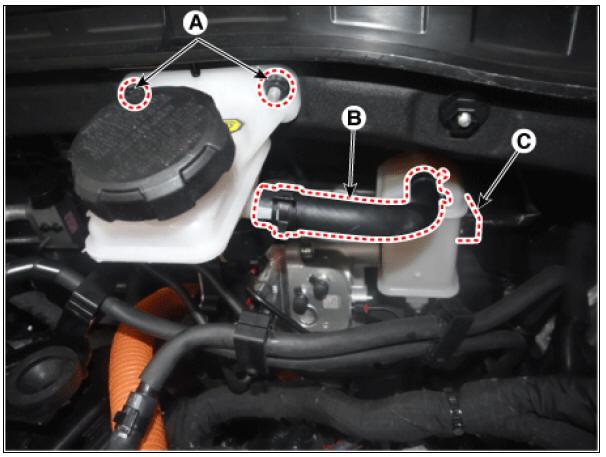
- Remove the nuts (A), hose (B), brake fluid level sensor connector (C).
Tightening torque: 6.8 - 10.7 N*m (0.7 - 1.1 kgf*m, 5.0 - 7.9 lb*ft)
- Disconnect the integrated brake actuation unit (IBAU) connector (A) and brake tube (B).
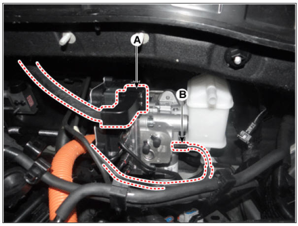
- Loosen the flare nuts (A) from the integrated brake actuation unit (IBAU) and then remove the brake tube.
Tightening torque: 12.7 - 16.7 N*m (1.3 - 1.7 kgf*m, 9.4 - 12.3 lb*ft)
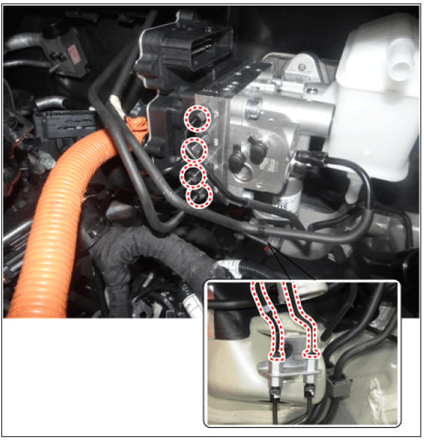
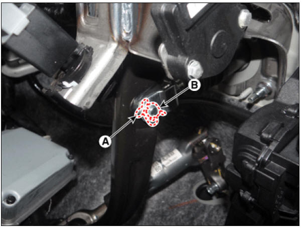
- Remove the snap pin (A) and clebis pin (B).
- Loosen the brake pedal nuts.
Tightening torque : 16.7 - 25.5 N*m (1.7 - 2.6 kgf*m, 12.3 - 18.8 lb*ft)

Installation
- Installation is the reverse of removal.
- Check the brake pedal operation.
- After filling the brake fluid in the reservoir, perform the air bleed.
(Refer to the Brake system - "Brake Bleeding Procedure")
- Conduct the variant coding.
- Conduct the pedal traval sensor (PTS) calibration.
- Conduct the longitidinal G sensor clibration. (HAC/DBC Only)
- Conduct the pressure sensor calibration.
- Conduct the auto detected configuration reset the if necessary.
Diagnosis by using diagnostic device
The following section describes how to diagnose faults using a diagnostic instrument
- Connect self-diagnosis connector (16pins) located under the driver side crash pad to self-diagnosis device, and then turn the selfdiagnosis device after key is ON.
- Select the "vehicle model" and "ESC/AHB" on KDS vehicle selection screen.
- Proceed with the test according to the screen instructions.
Longitudinal G Sensor Calibration(HAC/DBC Only)

Pressure Sensor Calibration

Pedal Travel Sensor (PTS) Calibration

Auto Detected Configuration Reset(ESP(ESC) Only)

ESC Variant Coding

READ NEXT:
 Pressure Source Unit Repair procedures
Pressure Source Unit Components and components location
Components
Warning
PSU (Presser Source Unit) must not be disassembled.
Pressure Source Unit (PSU)
Pressure Source Unit (PSU) connector
Motor
Filler adapter
Bracket
Accumulat
The Air Cleaner
Element
Inspection
Remove the air cleaner element.
Check that the air filter is excessively dirty.
If the air filter is excessively dirty, replace the air cleaner element.
If the air cleaner element needs to be cleaned, blow compressed air as
SEE MORE:
CVVT & Camshaft Description and operation
Description
Continuous Variable Valve Timing (CVVT) system advances or retards the valve
timing of the intake and exhaust valve in accordance with the ECM control signal
which is calculated by the engine speed and load.
By controlling CVVT, th
Driving in the rain
Rain and wet roads can make driving
dangerous, especially if you're not prepared
for the slick pavement.
Here are a few things to consider when
driving in the rain:
A heavy rainfall will make it harder to
see and will increase the dis
Categories
- Home
- KIA Niro EV, Hybrid - Second generation - (SG2) (2021-2024) - Owner's manual
- Kia Niro - First generation - (DE) (2017-2022) - Service and Repair Manual
- Contact Us