KIA Niro: Oil Cooler Repair procedures | Oil Pressure Switch Repair procedures
Removal
- Remove the engine room under cover.
(Refer to Engine and Transaxle Assembly - "Engine Room Under Cover")
- Drain the engine oil and then remove the oil filter.
(Refer to Lubrication System - "Engine Oil")
- Drain the coolant.
(Refer to Cooling System - "Coolant")
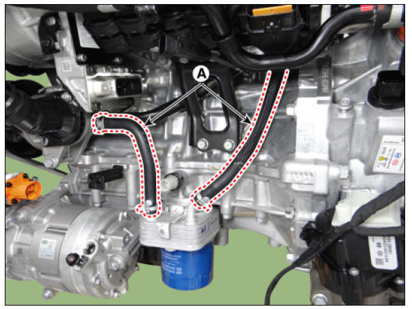
- Disconnect the coolant hose (A).
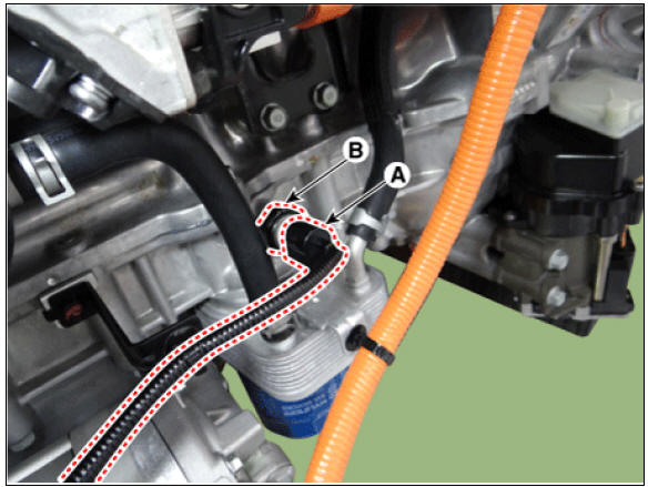
- Unfasten the fixing bolt (A) and then remove the oil cooler assembly (B).

Installation
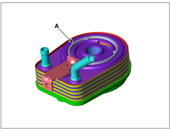
- Apply engine oil to the oil cooler packing surface (A).
- Install the oil cooler (A) with a fixing bolt (B).
Tightening torque : 50.1 - 55.9 N*m (5.1 - 5.7 kgf*m, 36.9 - 41.2 lb*ft)

Warning
Fix position of oil cooler stopper where oil cooler resists on ladder frame stopper.
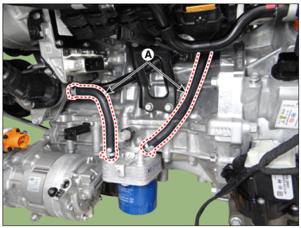
- Connect the coolant hose (A).
- Fill the coolant.
(Refer to Cooling System - "Coolant")
- Install the oil filter and then fill the engine oil.
(Refer to Lubrication System - "Engine Oil")
- Install the engine room under cover.
(Refer to Engine and Transaxle Assembly - "Engine Room Under Cover")
Oil Pressure Switch Repair procedures
Removal and
Installation
- Disconnect the battery negative terminal.
- Remove the engine room under cover.
(Refer to Engine and Transaxle Assembly - "Engine Room Under Cover")
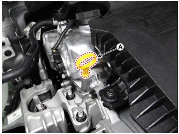
- Disconnect the oil pressure switch connector (A).
- Remove the oil pressure switch (B).
Tightening torque : 9.8 - 11.8 N*m (1.0 - 1.2 kgf*m, 7.2 - 8.7 lb*ft)
- Install in the reverse order of removal.
Warning
When installing the oil pressure switch, apply seal lock to the thread.
Seal lock : THREEBOND 2403
Thickness : 0.2 - 0.4 mm (0.008 - 0.016 in.) 
Inspection
- Check the continuity between the terminal and the body with an ohmmeter.
If there is no continuity, replace the oil pressure switch.
- Check the continuity between the terminal and the body when the fine wire is pushed. If there is continuity even when the fine wire is pushed, replace the switch.
- If there is no continuity when a pressure of 50 kPa (0.50 kgf/cm², 7.25 psi) is applied through the oil hole, the switch is operating properly.
Check for air leakage. If air leaks, the diaphragm is broken. Replace it.

Oil Level Gauge & Pipe Repair procedures
Removal and
Installation
- Remove the oil level gauge (A).
- Remove the timing chain cover.
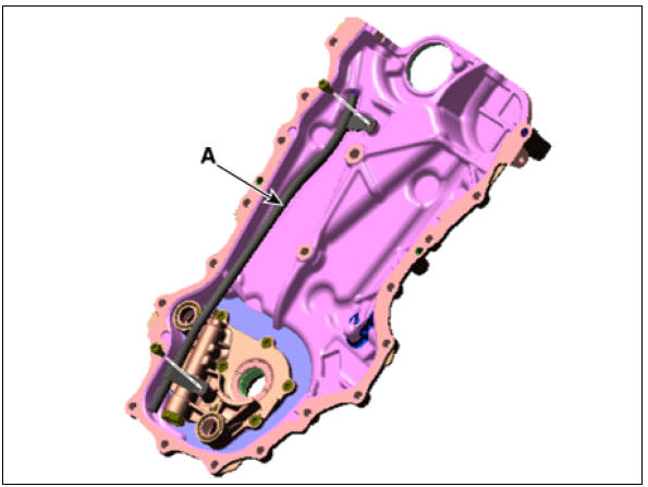
(Refer to Timing System - "Timing Chain Cover") 3. Remove the Oil level gauge pipe (A).
Tightening torque : 8.8 - 13.7 N*m (0.9 - 1.4 kgf*m, 6.5 - 10.1 lb*ft)
- Install in the reverse order of removal.
Removal and
Installation
Warning
Do not disassemble the oil pump (A) from timing chain cover because it is supplied as timing chain cover & oil pump assembly. 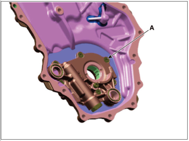
READ NEXT:
 Front Oil Seal Repair procedures | Timing Chain Cover Repair procedures
Components
Front oil seal
Timing chain cover
Variable force solenoid (VFS) valve
O-ring
Timing chain tensioner
Timing chain tensioner arm
Timing chain guide
Timing chain
Timing chain cam guide
Front
SEE MORE:
Heated steering wheel
Operation
Press the button to turn the heated
steering wheel ON or OFF.
The heated steering wheel reverts to
the OFF position whenever the vehicle
is restarted.
Operating condition(s) (Kia Niro EV)
The vehicle should be i
Hitches
It's important to have the correct hitch
equipment. Crosswinds, large trucks
going by, and rough roads are a few reasons
why you'll need the right hitch.
Here are some rules to follow:
Do you have to make any holes in the
body of
Categories
- Home
- KIA Niro EV, Hybrid - Second generation - (SG2) (2021-2024) - Owner's manual
- Kia Niro - First generation - (DE) (2017-2022) - Service and Repair Manual
- Contact Us