KIA Niro: Hybrid Starter Generator(HSG)
Component location
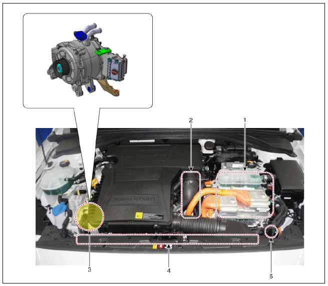
- HPCU (Hybrid Power Control Unit) (LDC+MCU+HCU+Reservoir)
- Hybrid drive motor
- Hybrid starter generator (HSG)
- Electrical radiator
- Electric water pump (EWP)
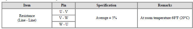
Specification

Inspection
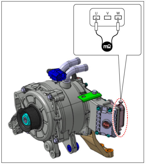
- Inspect the line to line resistance using mΩ tester.
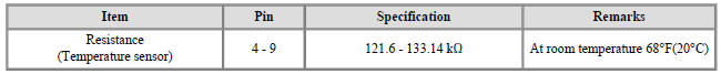
- Inspect the temperature sensor resistance.
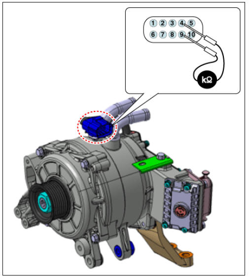
- Inspect the resolver sensor resistance.
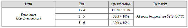
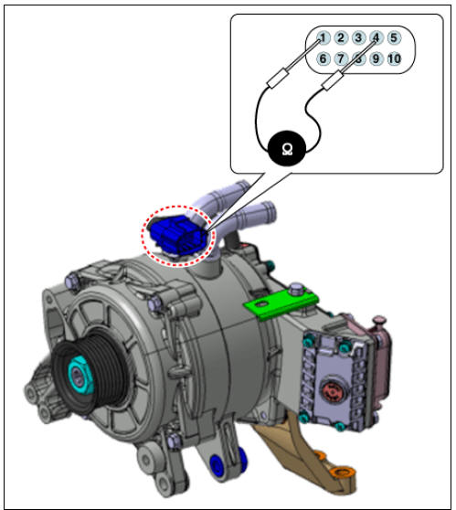
- Inspect the insulation resistance.

Removal
Warning
- Be sure to read and follow the "General Safety Information and Caution" before doing any work related with the high voltage system. Failure to follow the safety instructions may result in serious electrical injuries.
- Be sure to shut off the high voltage circuit according to the "High Voltage Shut-off Procedures" before doing any work related with the high voltage system to avoid serious electrical injuries.
- Shut off the high voltage circuit.
( Refer to Hybrid Motor System - "High Voltage Shut-off Procedure")
- Drain the coolant from the hybrid cooling system.
(Refer to Hybrid Motor Cooling System - "Coolant")
- Remove the air cleaner assembly.
(Refer to Engine Mechanical System - "Air Cleaner")
- Remove the drive belt.
(Refer to Engine Mechanical System - "Drive Belt")
- Remove the drive belt tensioner.
(Refer to Engine Mechanical System - "Drive Belt Tensioner")
- Remove the idler.
(Refer to Engine Mechanical System - "Idler")
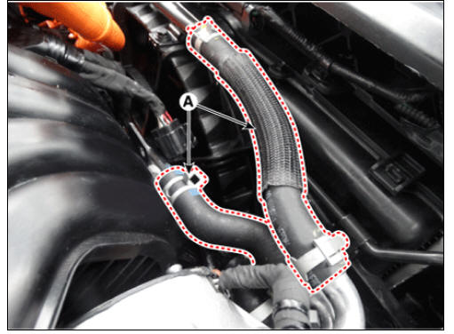
- Disconnect the HSG connector (A).
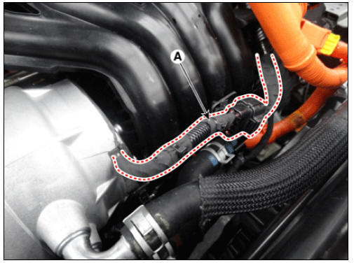
- Disconnect the cooler hose (A) from the HSG.
- Remove the intake manifold.
(Refer to Engine Mechanical System - "Intake Manifold")
- Loosen the HSG mounting nut (A) and bolt (B).
Tightening torque : 44.1 - 49.0 N*m (4.5 - 5.0 kgf*m, 32.5 - 36.2 lb*ft)
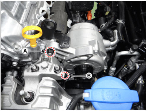
- Remove the HSG after removing the HSG bracket (A).
Tightening torque : 55.9 - 60.8 N*m (5.7 - 6.2 kgf*m, 41.2 - 44.8 lb*ft)

Installation
- Install in the reverse order of removal.
Warning
- Be careful not to damage other hoses nearby when tightening the clamp.
- Install the clamp in the specified direction to prevent interference with surrounding components
- Perform the procedure below after installing.
(1) Refill the hybrid cooling system with coolant and bleed air from the hybrid cooling system using KDS.
(Refer to Hybrid Motor Cooling System - "Coolant") (2) Perform the engine clutch / motor resolver adaptation using the KDS.

READ NEXT:
 Hybrid Motor Control System
Description
The Hybrid Power Control Unit (HPCU), composed of various components, is
the core device among the Power Electronics
devices that acts as the brain.
It comprises of the Hybrid Control Unit (HCU), an inverter Motor Control
Un
Resolver Sensor | Motor Temperature Sensor
Description
The accurate position of the rotor must be known at all times to ensure maximum output control of the motor.
Part Circuit Diagram
Hybrid Drive Motor
HSG
Resolver Sensor Repair procedures
Inspection
Hybrid Drive Motor
SEE MORE:
DC Fuse
Component Location
DC Fuse
Inverter Connector (↔ Power Relay Assembly (PRA))
Inverter Connector (↔ Electric A/C compressor)
Component Location
Harness Connector
DC Fuse Repair procedures
Removal
Warning
Be sure to rea
Voltage Check
Warning
Be sure to read and follow the "General Safety Information and
Caution" before doing any work related with the high
voltage system. Failure to follow the safety instructions may result in serious
electrical injuries.
Measu
Categories
- Home
- KIA Niro EV, Hybrid - Second generation - (SG2) (2021-2024) - Owner's manual
- Kia Niro - First generation - (DE) (2017-2022) - Service and Repair Manual
- Contact Us